Introduction
The cost of a poorly specified switchboard isn't abstract—it's measured in compliance failures, costly retrofits, multi-week project delays, and field rejections that cascade through the schedule. A switchboard undersized by 20% requires replacement, not upgrade. An AIC rating that falls short of available fault current creates a life-safety hazard and fails inspection. A NEMA 1 enclosure installed outdoors voids the warranty before energization.
Whether the project is a data center, industrial plant, commercial building, or healthcare facility, the switchboard specification determines system safety, schedule integrity, and long-term operational reliability. This guide covers the critical specification parameters — from ampacity and AIC ratings to enclosure type and lead times — so engineers, contractors, and facility teams can make informed decisions before equipment is ordered.
According to industry analysis, contractors must now project equipment needs far in advance: switchboards with molded case circuit breakers up to 2,500A carry 52-week lead times, while power circuit breaker assemblies 3,000A and above require 84+ weeks. Getting the specification right from the start keeps projects on schedule and avoids the compounding costs of rework.
Key Takeaways
- Switchboards distribute power from utility or generator sources to facility circuits; wrong specifications lead to overloads, code violations, and costly field changes
- Calculate voltage, bus amperage, and AIC rating from actual load data per NEC Article 220 before ordering
- UL 891 certification and NEMA enclosure ratings must match your safety standards and installation environment
- Physical layout (dimensions, cable entry, working clearance) must align with NEC 110.26 before manufacturing begins
- Custom switchboard lead times can stretch 12+ months, so early supplier engagement is critical to keeping projects on schedule
What Is an Electrical Switchboard?
A switchboard is a dead-front assembly of busbars, overcurrent protection devices, and metering equipment that receives power from a utility or generator source and distributes it to downstream circuits. Operating at voltages typically up to 600V in the US (UL 891 covers assemblies up to 1000V), switchboards serve as the central hub for facility power management.
Dead-front construction means no live parts are exposed to operators on the front of the equipment, allowing routine monitoring and breaker operation without risk of accidental contact with energized busbars. This design standard, governed by UL 891, distinguishes modern commercial switchboards from older live-front panels.
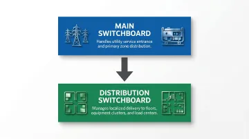
Most projects require two board types, each serving a distinct role in the power hierarchy:
- Main switchboards receive power from the utility service entrance and distribute to the facility's primary zones
- Distribution switchboards manage localized power delivery to specific floors, equipment clusters, or load centers downstream from the main board
Most commercial and industrial projects require both in a hierarchical layout, with the main board handling utility coordination and distribution boards providing zone-level control and protection.
Key Electrical Specifications to Define Before You Order
Electrical specification errors—wrong voltage class, undersized bus, insufficient fault current rating—rank among the most common causes of change orders, installation delays, and failed inspections on power distribution projects. Each parameter must be calculated, not estimated, before equipment is ordered.
Voltage Class and System Configuration
Most commercial projects run on 480Y/277V for large systems (HVAC, EV charging, industrial loads) stepped down to 208Y/120V for lighting and receptacles. Industrial and data center applications can reach 600V or 800V, with 800V emerging in data centers to improve efficiency and reduce power loss across longer distribution runs.
Selecting the wrong voltage class creates compatibility problems costly to correct once equipment is ordered. Motors specified for 480V won't operate on 208V systems, and protective devices must match the voltage class to function correctly.
System configuration (delta vs. wye) affects:
- Wye-connected systems provide a neutral conductor for solidly grounded installations; delta systems require corner-grounded or ungrounded approaches
- Neutral conductors in wye systems must be sized to handle harmonic currents and unbalanced loads
- Ground-fault protection settings and coordination schemes depend directly on system grounding type
Main Bus Amperage and Load Calculations
Main bus amperage must be sized to the total calculated load of the facility, not just the connected load. Specifiers should work with an engineer to perform a full NEC Article 220 load calculation, then size the bus with appropriate headroom for future expansion.
Proper sizing avoids two equally costly mistakes:
- Undersizing creates overheating risk and code violations that require equipment replacement
- Oversizing adds unnecessary upfront cost without improving performance or safety
Typical switchboard bus ratings run from 400A to 4,000A, with UL 891 assemblies available up to 12,000A for large-scale applications. Load analysis should apply NEC demand factors to reflect the statistical diversity of simultaneous operation—not assume every circuit draws full load at once.
Engineers typically add a minimum of 25% headroom above the calculated load when sizing the bus, preserving capacity for future circuit additions without requiring a full switchboard replacement.