
Introduction
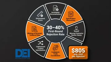
Electrical switchgear submittals represent the last line of defense before equipment is procured and installed. A missed specification in the submittal can mean weeks of delays, costly change orders, or non-compliant equipment in the field. According to BuildSync's analysis of over 6,000 construction professionals, each rejected submittal costs an average of $805 when accounting for labor hours and coordination time. On a typical $50M commercial building, with approximately 2,000 submittals and a 30-40% first-submission rejection rate, annual rejection costs can reach $563,500.
Switchgear lead times already run 6-10 weeks for standard configurations, 12-16+ weeks during supply chain disruptions, and up to 16-26 weeks for custom-engineered assemblies or BABA-compliant sourcing. Every submittal rejection adds directly to that timeline.
This guide walks contractors, engineers, and facility teams through what to look for in a switchgear submittal package, how to verify technical compliance, and how to move forward when issues arise.
Key Takeaways
- Complete submittals require manufacturer cut sheets, a single-line diagram, equipment schedule, UL/NEMA certifications, and protective relay settings — missing any of these triggers rejection
- Cross-check every submittal item against project specifications, electrical drawings, and applicable code standards
- Pay closest attention to voltage rating, ampacity, interrupting capacity (kAIC), and bus configuration—these drive most rejections
- UL 891 certification for low-voltage switchboards is non-negotiable — if the listing isn't confirmed in the submittal, reject it
- Each rejection adds 2–3 weeks to the schedule, since resubmittals typically take another 16–31 days to process
What a Complete Switchgear Submittal Package Should Include
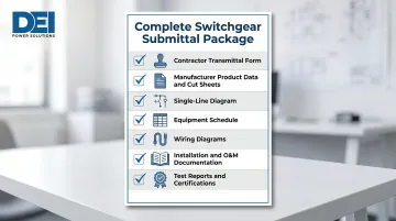
Reviewing a switchgear submittal begins with confirming the package is complete. Return any incomplete submittal before technical review starts — this enforces accountability and keeps the review process efficient.
Required documents include:
- Contractor transmittal form with review stamp
- Manufacturer product data and cut sheets
- Single-line diagram
- Equipment schedule
- Wiring diagrams
- Installation and O&M documentation
- Test reports or certifications (UL listing, seismic, NEMA)
Contractor Review Stamp Requirement
The general contractor or electrical subcontractor must review and stamp the submittal before it reaches the engineer or facility team. Per AIA Document A201 Section 3.12.5, the contractor is required to determine and verify materials, field measurements, and field construction criteria, and to check and coordinate submittal information against the Contract Documents.
Returning an unstamped submittal is the correct call. It ensures the contractor has done the preliminary verification work before the design team commits any review time.
Equipment Schedule and Single-Line Diagram Requirements
Once contractor accountability is confirmed, the next step is verifying the technical content. The equipment schedule and single-line diagram must show:
- Each switchboard or switchgear section labeled by tag number
- Voltage class (e.g., 480V, 208V, 600V)
- Ampere rating of main bus and each section
- Number of phases (3-phase vs. single-phase)
- Fault current rating (SCCR and kAIC)
- Feeder and branch circuit assignments
These must match the contract drawings exactly. Any discrepancy between the submittal and the project drawings warrants rejection or a revision request.
Key Technical Specifications to Verify in a Switchgear Submittal
Technical verification is the highest-risk step. Reviewers are cross-referencing dozens of data points across manufacturer cut sheets and project specs. A single missed specification—such as a wrong interrupt rating—can result in a non-compliant installation that fails commissioning or endangers personnel.
Voltage Rating, Ampacity, and System Configuration
Verify that the submitted equipment matches:
- Specified system voltage (e.g., 480V, 208V, 600V)
- Ampere rating of the main bus and each section
- Number of phases (3-phase vs. single-phase)
- System grounding (solidly grounded, high-resistance grounded, or ungrounded)
Mismatches here are an automatic rejection. These parameters define the fundamental compatibility between the switchgear and the electrical system.
Short Circuit and Interrupting Capacity
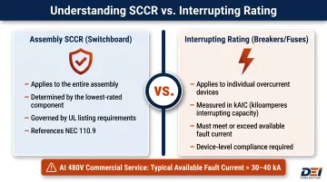
Confirm that the short circuit current rating (SCCR) and the interrupting capacity of every overcurrent device (in kAIC) meet or exceed the available fault current stated in the project's power system study or utility coordination report.
NEC 110.9 states: "Equipment intended to interrupt current at fault levels shall have an interrupting rating at nominal circuit voltage at least equal to the current available at the line terminals of the equipment."
Undersized interrupting ratings are a safety code violation under NEC 110.9 and a common reason for engineering rejection. At 480V commercial service entrances, available fault currents typically fall between 30 kA and 40 kA, depending on transformer size and impedance. Always verify against site-specific calculations or utility data, not assumed values.
Key distinction: Per UL, Short-Circuit Current Rating (SCCR) applies to the entire assembly (the switchboard), while interrupting rating applies to individual overcurrent protective devices (breakers, fuses). The overall panel SCCR is determined by the lowest-rated component in the power circuit.
Bus Configuration and Feeder Distribution
Check that busbar ampacity, material (copper vs. aluminum), and configuration all match specifications. Confirm:
- Number of distribution sections
- Feeder breaker sizes
- Circuit assignments align with the one-line diagram
Flag any substitution from copper to aluminum bus as a deviation requiring design team approval. Material changes affect thermal performance, expansion characteristics, and connection details.
Metering, Controls, and Protective Relay Settings
Metering devices, instrument transformers (CT/VT ratios), and protective relay or electronic trip unit settings must all be specified in the submittal and reconciled against the coordination study. Check:
- Control voltage (24VDC, 120VAC, etc.)
- Communication protocol (Modbus, BACnet, etc.) if specified
- Relay settings match the coordination study time-current curves
If relay settings are absent or mismatched, return the submittal with a specific rejection note requesting the coordination study overlay before resubmission.
Physical Dimensions, Clearances, and Installation Details
Check that submitted equipment dimensions, weight, and footprint match the space allocation on architectural/electrical drawings. Confirm required front/rear access clearances comply with NEC 110.26 minimums:
| Voltage to Ground | Condition 1 | Condition 2 | Condition 3 |
|---|---|---|---|
| 0-150V | 3 ft | 3 ft | 3 ft |
| 151-600V | 3 ft | 3 ft 6 in | 4 ft |
Per NEC 110.26(A)(1), width must be minimum 30 inches or width of equipment (whichever is greater), and headroom must be minimum 6 ft 6 in. Equipment rated 1200A or more and over 6 ft wide requires at least two entrance/exit paths.
Any dimensional deviation that would prevent installation in the specified location requires rejection and design team coordination before resubmission.
Certifications and Compliance Documentation to Check
Certifications are non-negotiable. A listed mark proves the equipment has been independently tested to a recognized standard, and code authorities (AHJ) will require proof of listing before permitting or final inspection. The submittal must include documentation of all applicable certifications, not just a reference to them in text.
Key Listing Standards for Low-Voltage Switchgear
UL 891 - Switchboards: Covers dead-front switchboards up to 600V (for configurations under 2000A) or 480V (up to 4000A). Tests for short-circuit current ratings (up to and beyond 100 kA), temperature rise, and continuous current ratings. This is the most common standard for this equipment in North America.
UL 508A - Industrial Control Panels: Covers industrial control panels (ICPs) for general industrial and machinery applications, governed by NEC Article 409. Does NOT cover main power distribution assemblies (which fall under UL 891 or UL 1558). Requires SCCR calculation per Supplement SB.
NEMA PB 2 - Deadfront Distribution Switchboards: Covers floor-mounted deadfront switchboards rated 6000 amperes or less, 600 volts or less, consisting of molded case circuit breakers. Complements UL 891 by providing NEMA-specific construction and performance standards.
NEC Compliance References
The equipment must be listed and labeled per NEC 110.2 — which requires that conductors and equipment be approved before use — and overcurrent protection must comply with Articles 240, 408, and 230 as applicable. The AHJ typically relies on third-party certification marks from Nationally Recognized Testing Laboratories (NRTLs) as the basis for approval.
Key NEC Article 408 provisions to verify:
- 408.6: Available fault current and calculation date must be field-marked on the enclosure (non-dwelling units)
- 408.4(B): Source of supply marking required (non-dwelling), must be permanent and non-handwritten
- 408.4(A): Circuit directory required; must be clear, specific, and permanent
Project-Specific Compliance Requirements
Beyond standard code requirements, some projects carry additional compliance obligations that must be documented in the submittal.
BABA (Build America, Buy America) Compliance: Required for federally funded infrastructure projects. For electrical equipment like switchgear, the product must be manufactured in the United States. In the submittal, look for a domestic-origin declaration or a signed BABA compliance letter from the manufacturer. Waivers are available through a public comment process.
Seismic Qualification: ASCE/SEI 7-22 Chapter 13 establishes seismic design requirements for nonstructural components. Electrical equipment (classified as an "active" component) must be certified to maintain operability after a design earthquake. Shake-table testing per ICC-ES AC156 is the standard method for seismic certification. Enforcement varies by jurisdiction and AHJ.
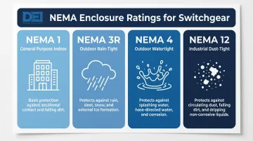
NEMA Enclosure Rating: Verify the enclosure rating matches the installation environment:
- NEMA 1: Indoor, general purpose
- NEMA 3R: Outdoor, rain-tight
- NEMA 4: Outdoor, watertight
- NEMA 12: Industrial, dust-tight
Arc Flash Labeling: NFPA 70E Section 130.5(H) requires labels on nonresidential electrical equipment likely to be examined, adjusted, serviced, or maintained while energized. Labels must include nominal system voltage, arc flash boundary, and either available incident energy/working distance or arc flash PPE category.
Warranty, O&M Manuals, and Factory Test Reports
Confirm that warranty documentation, O&M manuals, and factory test reports are included or committed to in the submittal. These are required for project closeout and are often missing from first-round submittals. Any commitment should be in writing — a delivery schedule tied to project milestones, not a verbal assurance. A submittal that lists these documents as "to follow" without a date is a flag worth pushing back on before approval.
How to Interpret Submittal Findings: Approve, Flag, or Reject
Every discrepancy found during review must be categorized before a response is issued. Rushing to reject everything or approving with vague notes wastes time and creates disputes. Each finding needs a specific response — approve, flag for revision, or reject — with a documented reason tied to the contract documents.
Approve / No Exceptions
Full approval is warranted when:
- All technical specifications match contract documents
- All required certifications are confirmed
- Equipment dimensions and configuration align with drawings
- No substitutions are proposed
Even approved submittals should be stamped with the reviewer's notation and filed as part of the permanent project record. Under AIA A201 Section 4.2.7, the reviewer's role is limited to checking conformance with the design concept in the Contract Documents — not verifying every field condition or installation detail.
Approve with Exceptions / Revise and Resubmit
Minor deviations can often be resolved with a noted exception or a revision request rather than outright rejection. Examples include:
- A substituted breaker brand that meets all electrical specifications
- A dimensional difference within acceptable tolerances
- Minor material substitutions that don't affect performance
The reviewer should document the specific deviation, cite the affected specification section or drawing detail, and include either:
- Explicit approval of the deviation (with conditions if applicable)
- A request for additional documentation to support the deviation
The key distinction from rejection: The equipment is fundamentally compliant; the issue is minor and resolvable without starting over.
Reject and Return
Rejection is warranted for:
- Incorrect voltage or ampere rating
- Insufficient interrupting capacity (violates NEC 110.9)
- Missing UL listing or certification documentation
- Unacceptable bus material substitution without approval
- Missing critical documentation (single-line, relay settings, seismic certification)
The rejection notice must cite the specific spec section or drawing reference being violated. Vague rejections create confusion and delay resubmission. Use language like:
- "Rejected: Submitted 30 kAIC rating does not meet Section 26 05 13, Para. 2.3.B requirement for 42 kAIC minimum per power system study dated [date]."
- "Rejected: UL 891 listing documentation not provided. Submit UL file number and listing card per Section 26 24 13, Para. 1.4.A."
Common Mistakes When Reviewing Switchgear Submittals
The most consequential reviewer error is approving a submittal based on the cover sheet alone. Manufacturers routinely include multiple model variants in a single cut sheet — so confirming that the exact model number matches the specification, not just the product family, is a non-negotiable step.
Failing to Cross-Reference Drawings AND Specifications
Drawings may show a circuit configuration, but specifications set the performance and listing requirements. Missing either reference source leads to incomplete review and downstream field conflicts. Always verify against both:
- Drawings: for tag numbers, circuit assignments, physical layout, clearances
- Specifications: for performance requirements, listing standards, materials, testing
Accepting Submittals Without Contractor Review Stamp or Undisclosed Substitutions
Once approved, any deviation becomes the project of record. Per AIA A201 Section 3.12.8, the contractor is not relieved of responsibility for deviations from the Contract Documents even if the architect approves the submittal — and correcting a non-specified product after installation costs far more than returning the submittal for correction upfront.
Industry data indicates 30-40% of construction submittals are rejected on first submission. The seven root causes are:
- Incomplete documentation
- Specification mismatches
- Missing contractor review stamp
- Inadequate coordination between trades
- Substituted products submitted without formal substitution requests
- Missing or incorrect technical data
- Dimensional errors
Frequently Asked Questions
How to review electrical submittals?
Start by confirming the package is complete: transmittal, cut sheets, certifications, and single-line diagram. Then cross-check all technical data against the project specifications and drawings, categorizing findings as approve, revise, or reject with specific code or spec citations for any discrepancies.
What are the three main reasons submittals are rejected?
The three most common causes are non-compliant technical specifications (wrong voltage, ampacity, or interrupt rating), missing or unconfirmed certifications (no UL listing documentation), and undisclosed substitutions of specified products without equivalency documentation or formal substitution request approval.
How to interpret an electrical drawing?
Start with the single-line diagram, which shows system topology, ratings, and breaker assignments. Then cross-reference the equipment schedule for tag numbers, and compare plan drawings for dimensional and clearance requirements to confirm everything aligns.
What should be included in a switchgear submittal package?
A complete package includes:
- Manufacturer product data and cut sheets
- Single-line diagram and equipment schedule
- Wiring diagrams
- UL listing documentation and short circuit/interrupt ratings
- O&M manuals (or a written commitment to deliver them at closeout)
All documents must carry the contractor's review stamp before submission.
What does UL 891 mean on a switchgear submittal?
UL 891 is the standard for deadfront switchboards covering construction, ratings, and safety requirements. Seeing it on a submittal means the equipment has been independently tested and listed, which is required by NEC 110.2 and typically required by the AHJ before permit approval.
What happens if a switchgear submittal is rejected?
A rejected submittal requires the subcontractor to revise and resubmit, restarting a review cycle that takes 16–31 days on average. With switchgear lead times of 6–10 weeks (or 16–26+ weeks for custom configurations), even a single rejection round can push delivery past critical project milestones.