Introduction
A 600 amp commercial service installation ranks among the most technically demanding electrical projects in the commercial sector. It requires precise load calculations, NEC-compliant conductor and conduit sizing, utility coordination, and execution by licensed professionals. Errors carry real consequences — for safety, schedule, and budget.
Who handles this work: Licensed master electricians, electrical contractors, and engineers with commercial installation experience manage design and execution. Facility teams and project managers coordinate permits, utility timelines, and inspection schedules.
The cost of getting it wrong is steep. According to NFPA data, 16,930 non-home structure fires per year involve electrical distribution and lighting equipment — causing $718 million in annual property damage. Common failure points include:
- Undersized conductors that overheat under load
- Improper grounding that creates shock and fire hazards
- Poor terminations that trigger arc faults
- Failed inspections that force costly rework and blow project schedules
Key Takeaways
- 600A commercial service must comply with NEC Articles 230, 250, and 310—and requires a licensed electrician for legal installation
- Parallel conductors (two 350 kcmil copper per phase) are the standard approach—single 1,500 kcmil pulls are rarely practical
- Grounding electrode conductor minimum is 3/0 AWG copper; equipment grounding conductor is 1 AWG copper
- UL 891-listed switchboards reduce field errors and ensure code compliance
- AHJ inspection before utility energization is mandatory; skipping it stalls the project at the finish line
Planning and Prerequisites for a 600 Amp Commercial Service
A 600 amp service is not a default choice—it's selected based on calculated load demand. This service level suits large commercial buildings, multi-tenant office complexes, small-to-mid manufacturing facilities, data centers, healthcare facilities, and campuses with significant HVAC, lighting, and process loads.
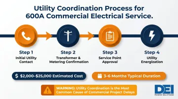
Load Calculation and Utility Coordination
A formal electrical load calculation per NEC Article 220 must be completed before any design work begins. If calculated load falls below 400 amps, a 600A service is oversized for the application and hard to justify on cost.
Service capacity by voltage:
- 600A at 208Y/120V provides approximately 216 kVA
- 600A at 480Y/277V provides approximately 499 kVA
Utility coordination timeline: Contact the serving utility to confirm transformer availability, service point location, metering requirements, and equipment specifications. Utility coordination adds $2,000 to $25,000 and extends timelines by 3 to 6 months—this is typically the longest lead item and most common cause of project delays.
Permitting and Code Requirements
A commercial 600A service requires an electrical permit from the local Authority Having Jurisdiction (AHJ) before work begins. The permit package typically includes:
- Load calculation worksheet
- One-line diagram
- Equipment cut sheets
- Site/riser diagram
Key NEC articles governing this work (2023 Edition):
- Article 230 - Services (entrance conductors, wiring methods, disconnects)
- Article 250 - Grounding and bonding
- Article 310 - Conductor sizing and ampacity
- Article 220 - Load calculations
Local amendments may impose stricter requirements than base NEC. Always confirm with the AHJ before submitting your permit package.
Equipment and Switchboard Selection
With permits approved, equipment selection follows the engineer of record's distribution plan. The main distribution switchboard must include:
- Main breaker or disconnect rated at 600A minimum
- Bus ratings matching service ampacity
- Branch breaker provisions sized to the distribution plan
- UL 891 listing (specifically for switchboards)
Switchboard configuration—number of sections, branch positions, metering provisions—should be specified by the engineer of record.
Pre-engineered switchboards reduce field configuration errors and come with full UL 891 documentation ready for AHJ review. DEI Power, an approved Siemens OEM based in Ontario, California, manufactures UL 891-certified switchboards with 4–6 week lead times—faster than most field-assembled alternatives and with configuration handled before the unit ships.
Wire Sizing, Conduit, and Grounding Requirements
At 600A, no single standard wire size makes the decision automatic. Conductor selection involves a trade-off between single large-gauge pulls and parallel smaller-gauge runs, both permitted under NEC Article 310.10(H).
Conductor Sizing Options
Two strategies are available, each with distinct labor and material trade-offs.
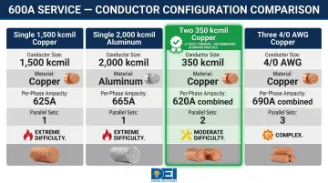
1. Single conductor per phase:
- Minimum 1,500 kcmil copper (rated 625A at 75°C)
- Or 2,000 kcmil aluminum (rated 665A at 75°C)
- Physically difficult to pull and terminate
- Connectors and lugs must be rated accordingly
- Pulling tension reaches 12,000 lbs per conductor, requiring heavy mechanical pullers
2. Parallel conductors per phase (more common):
- Two 350 kcmil copper per phase (310A × 2 = 620A)
- Or three 4/0 AWG copper per phase (230A × 3 = 690A)
- Parallel runs must be equal in length, conductor material, and raceway type per NEC 310.10(H)
| Configuration | Material | Per-Phase Ampacity | Parallel Sets | Installation Notes |
|---|---|---|---|---|
| Single 1,500 kcmil | Copper | 625A | None | Extremely difficult pull; 12,000 lbs tension |
| Single 2,000 kcmil | Aluminum | 665A | None | Requires larger conduit; specialized terminations |
| Two 350 kcmil | Copper | 310A each | 2 per phase | Most common commercial configuration |
| Three 4/0 AWG | Copper | 230A each | 3 per phase | Lower material cost but more complex installation |
Conduit Sizing
Conductor choice directly drives conduit sizing — larger or more numerous conductors require larger raceways to stay within NEC Chapter 9, Table 1's 40% maximum fill for three or more conductors. NEC Chapter 9 tables and Annex C fill calculations determine the specific sizes.
Typical conduit sizes for 600A parallel configurations:
- Two 350 kcmil THWN-2 conductors per phase per raceway: 2-inch RMC (at maximum fill capacity)
- Three 4/0 AWG THWN-2 conductors per conduit: 2-inch RMC accommodates up to 4 conductors
Three raceway types are commonly used at service entrance:
- RMC (Rigid Metal Conduit) — highest physical protection, required in many exposed installations
- IMC (Intermediate Metal Conduit) — lighter-weight alternative with equivalent protection ratings
- PVC Schedule 40/80 — permitted underground; Schedule 80 required where subject to physical damage
Grounding Electrode Conductor and Equipment Bonding
Per NEC Table 250.66, grounding electrode conductor minimums scale with the service conductor size:
- Service conductors over 1,100 kcmil copper: minimum 3/0 AWG copper or 250 kcmil aluminum
- Parallel 350 kcmil configuration (equivalent 700 kcmil): minimum 2/0 AWG copper or 4/0 AWG aluminum
Per NEC Table 250.122, equipment grounding conductor minimums at 600A overcurrent protection:
- Minimum 1 AWG copper or 2/0 AWG aluminum EGC
- When using parallel raceways, a full-sized EGC must be installed in each raceway
Two bonding rules apply regardless of conductor configuration:
- The neutral-to-ground bond must be made only at the main service disconnect — not at downstream panels
- All metal enclosures, conduit, and structural steel in the service equipment zone must be bonded per NEC Article 250 Part V
How to Install a 600 Amp Commercial Service: Step-by-Step
A 600A commercial service installation runs through five distinct phases. Skipping steps or working out of sequence introduces rework and real safety exposure — at this ampacity, mistakes are expensive and potentially dangerous.
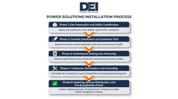
Prepare the Site and Coordinate Utility Work
Site preparation requirements:
- Confirm electrical room or pad location meets NEC 110.26 working clearance requirements (minimum 3 feet in front of equipment for 600V-class equipment)
- Verify structural slab or equipment pad supports switchboard weight
- Confirm conduit stub-up/stub-out locations align with utility and equipment plans
- Ensure construction sequence doesn't expose service equipment to weather or construction damage
Utility coordination at this stage:
- Schedule utility meter set and service transformer
- Confirm the service demarcation point — where utility responsibility ends and owner wiring begins
- Obtain utility's written approval of metering arrangement
Install Conduit and Pull Service Conductors
Conduit work sets the physical pathway for service conductors, so errors here compound through every subsequent phase.
Conduit installation sequence:
- Install service entrance conduit from utility point-of-delivery to main switchboard
- Include underground sections (direct burial vs. conduit-encased), sweeps, and weather heads for overhead service
- Seal and fire-stop all penetrations through walls and slabs per NEC 300.21 and applicable IBC fire-stopping requirements
Conductor pull requirements:
- For parallel runs, conductors in the same phase must be pulled in the same conduit or dedicated set
- At 600A, conductor pulls require mechanical pulling equipment — hand pulling is not feasible for large kcmil conductors
- Apply proper lubrication
- Observe maximum pulling tension limits and sidewall pressure constraints
Set and Anchor the Main Switchboard
Switchboard placement requirements:
- Set unit plumb and level
- Anchor per manufacturer's seismic/installation requirements
- Position to maintain all NEC 110.26 clearances
- For UL 891 switchboards, follow manufacturer's installation instructions (part of UL listing conditions)
Terminate Conductors and Complete Grounding
Termination sequence:
- Land conductors on main breaker or disconnect lugs using correct lug size and torque spec
- Always consult the manufacturer's lug torque table — undertorqued connections are a leading cause of arc faults at this ampacity
- Parallel conductors must be terminated in order (A-B-C-N across the bus)
- Label per NEC 230.66 and project drawings
With conductors landed, grounding and bonding ties the entire system to earth and ensures NEC-compliant fault current paths.
Grounding and bonding completion:
- Install grounding electrode conductor to grounding electrode system (ground rods, building steel, water pipe)
- Make neutral-to-ground bond at service disconnect
- Bond all metal enclosures and conduit systems
- Document every connection for inspection record
Complete Metering, Branch Distribution, and Pre-Energization Check
Before requesting utility energization, verify every system component is complete, covered, and visually inspected.
Final pre-energization steps:
- Install utility meter socket if owner-supplied
- Confirm all branch circuit wiring in switchboard is complete and correct
- Verify all unused breaker positions are covered
- Perform complete visual inspection before requesting utility energization
Once the visual inspection is signed off, the system is ready for utility coordination and initial energization — covered in the next section.
Post-Installation Checks and Pro Tips
Even after clean installation, the system must not be energized without structured validation.
Torque audit: Re-check all conductor terminations against manufacturer torque specifications using a calibrated torque wrench. NFPA 70B (2023 Edition) now mandates torque verification as an enforceable standard, not just a recommendation. Document results for the AHJ inspection log.
Insulation resistance testing: Perform a megohm test at 1,000V DC with minimum 100 megohm acceptance per NETA ATS specifications for 600V-class equipment before applying utility voltage.
AHJ inspection process: The inspector verifies:
- Working clearances
- Conductor sizing and labeling
- Grounding/bonding
- Equipment listing marks
- Permit compliance
Have the one-line diagram, equipment cut sheets, and torque log available on-site. Missing any of these documents is one of the most common reasons inspections fail.
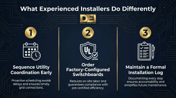
Three things experienced installers do differently:
- Sequence utility coordination early—utility timelines are typically the longest lead item
- Order the switchboard configured and factory-tested—pre-engineered UL 891-listed switchboards introduce less risk than field-assembled equipment
- Maintain a formal installation log documenting every major step, torque reading, and inspection outcome for warranty support and future maintenance
Common Installation Problems and Fixes
Voltage Drop on Long Service Runs
Problem: Excessive voltage drop (greater than the NEC-suggested 3% for feeders, 5% total) on services with long runs from utility point-of-delivery to switchboard. Common in campus or large-footprint commercial installations.
Cause: Undersizing conductors for run length without performing voltage drop calculation in addition to ampacity sizing.
Fix: Upsize service conductors beyond minimum ampacity requirement. Use NEC Chapter 9, Table 9 (conductor resistance: 350 kcmil copper = 0.043 ohm/kft) to calculate voltage drop and confirm sizing before conduit installation.
Overheating at Terminations
Problem: Termination points on main breaker or bus lugs run hot under load, triggering thermal alarm or breaker trip.
Cause: Undertorqued or improperly landed conductors—especially parallel conductors where one conductor bears disproportionate load.
Fix:
- Shut down and re-torque all terminations to manufacturer's specified values
- For parallel conductors, verify each conductor has equal length and equal lug engagement
- Schedule an infrared thermographic scan after commissioning to catch hidden hot spots
Grounding and Bonding Errors
Problem: Neutral-to-ground bond made downstream of the service disconnect (in a sub-panel), or missing bonding jumpers on metal conduit systems. Creates dangerous neutral current on ground paths.
Cause: Misunderstanding NEC Article 250 bonding requirements.
Fix:
- Verify neutral-ground bond exists only at the service disconnect
- Remove any downstream neutral-ground connections
- Install bonding bushings and jumpers on all metal conduit entering switchboard and downstream equipment
Correct all bonding errors before AHJ inspection — this is a common rejection point.
Conclusion
A 600 amp commercial service installation is a high-stakes project where quality of planning, conductor and conduit sizing, equipment selection, and installation execution directly affect how safe and long-lived the system will be. At this ampacity, cutting corners creates real fire and liability exposure — not just a code violation.
To protect the project and the end user:
- Source properly engineered, code-compliant equipment before breaking ground
- Engage the AHJ early — from permit submission through final inspection
- Document every stage of the installation for legal and operational protection
Skipping any of these steps at the 600A level rarely stays hidden. Poor installations surface as nuisance tripping, failed inspections, or equipment failures — all of them costlier to fix than doing it right the first time.
Frequently Asked Questions
How much does a 600 amp service cost?
600A commercial service installation costs range from $25,000 to $45,000 for mid-size commercial and production operations. Key cost drivers include switchboard equipment, conductor material, permits, utility coordination, and labor. Load calculation—not budget—should determine the appropriate service size.
Is there a 600 amp service?
Yes, 600A electrical service is a standard commercial and light industrial tier. It's used in large commercial buildings, multi-tenant facilities, manufacturing plants, and data centers where load demand exceeds 400A capacity.
What size wire is needed for a 600 amp service?
Two options exist: a single 1,500 kcmil copper conductor per phase (minimum single-conductor at 75°C), or parallel runs of two 350 kcmil copper conductors per phase. Parallel runs are more common in commercial practice — easier to pull, lower tension, and lower material cost.
What size grounding conductor do I need for a 600 amp service?
Per NEC Table 250.66, the grounding electrode conductor is typically 3/0 AWG copper or 250 kcmil aluminum for this service size. Per NEC Table 250.122, the equipment grounding conductor minimum is 1 AWG copper or 2/0 AWG aluminum at 600A overcurrent protection.
What size conduit is required for a 600 amp service?
Conduit size depends on conductor configuration. For the most common parallel-run configuration (two 350 kcmil THWN-2 conductors per conduit per phase), a 2-inch RMC conduit is required per NEC Annex C fill tables. RMC or IMC is standard for commercial service entrance raceways.
Do I need a permit to install a 600 amp commercial service?
Yes, an electrical permit from the local AHJ is required before any work begins. The permit package typically includes load calculation, one-line diagram, and equipment submittals. AHJ inspection must be completed and approved before the utility will energize the service.