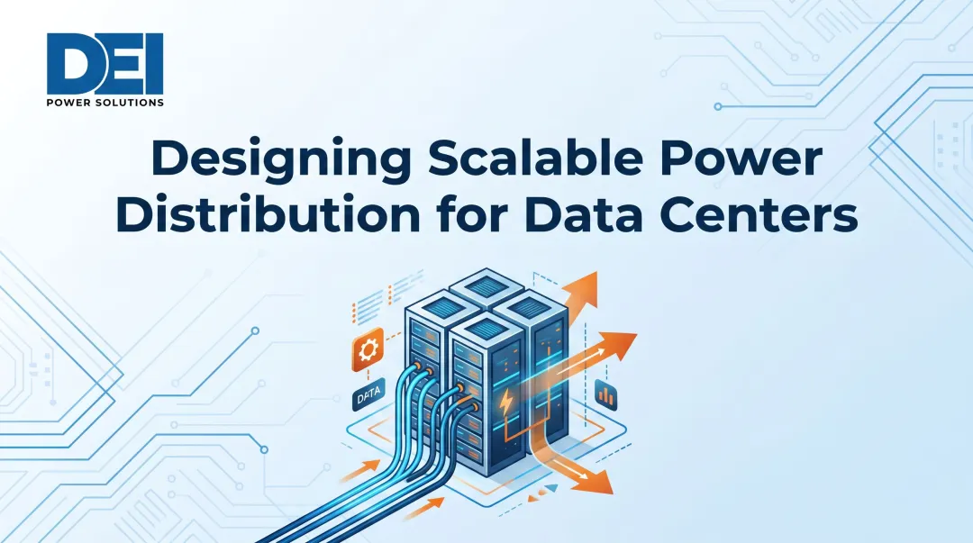
Most teams only scrutinize power distribution when something breaks. This guide walks through the complete chain—from utility grid to server rack—explaining what each component does, how power types differ, and what to look for when specifying equipment. Every link in this chain must be engineered correctly; a misconfigured switchboard or undersized PDU creates single points of failure that no amount of software redundancy can overcome.
Key Takeaways
- Data center power follows a fixed path: utility grid → transformers → low-voltage switchboards → UPS → PDUs → RPPs → server racks
- Critical components (UPS, PDUs, RPPs) deliver clean, uninterrupted power while protecting against voltage fluctuations and outages
- Three-phase AC power handles distribution across the facility; DC power handles UPS batteries and server-level conversion
- Redundancy models (N+1, 2N) prevent single-point failures — but only when designed into the power chain from the start
- UL 891 certification and correct voltage specification directly impact code compliance, inspection timelines, and long-term reliability
How Power Flows Through a Data Center
Understanding the sequential power path helps engineers make better decisions at every stage—from initial design through procurement and maintenance. Power doesn't simply "arrive" at servers; it travels through a carefully engineered chain: Utility Grid → Medium Voltage Switchgear → Step-Down Transformers → Low-Voltage Switchboards → UPS → PDUs → RPPs → Server Racks. Each stage adds protection, control, and distribution capacity.
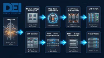
Utility Entry and Medium Voltage Distribution
Utilities deliver power at medium voltage—typically 13.8 kV to 34.5 kV—because high voltage reduces transmission losses over distance. At the facility boundary, medium voltage switchgear provides the first point of control and protection, allowing operators to isolate the data center from the grid during maintenance or faults. This equipment operates under IEEE C37 and ANSI C37.20.2 standards for metal-clad assemblies.
Transformer Step-Down and Low-Voltage Distribution
Transformers reduce incoming medium voltage to usable low voltages: 480V for facility mechanical systems and 208/120V for IT equipment. Low-voltage switchboards then split and route this power to different load categories—cooling, mechanical systems, and critical IT infrastructure. Proper switchboard configuration at this stage is foundational; errors here cascade through every downstream component.
Low-voltage switchboards must meet UL 891 certification to ensure code compliance and safe operation in mission-critical environments. UL 891 validates construction quality, fault current withstand ratings, and thermal performance under load. Without this certification, equipment often fails inspection, creating costly field corrections and project delays.
DEI Power builds UL 891-certified switchboards in Ontario, California to customer-specified voltage, layout, and ampacity. Assemblies use genuine Siemens components and ship pre-configured to spec, which avoids the field modifications that typically push timelines.
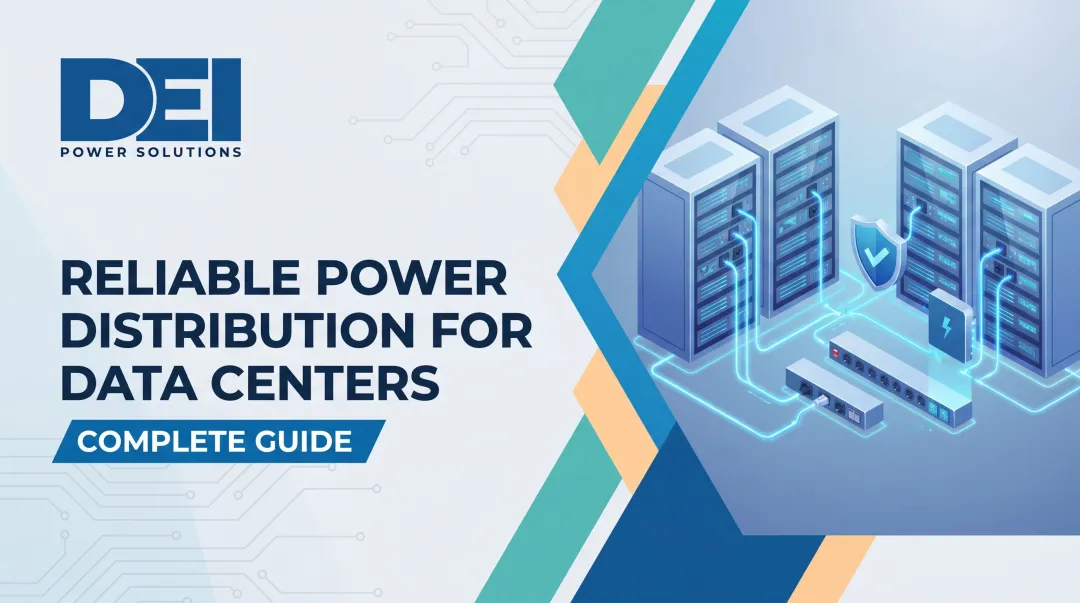
UPS, PDU, and RPP: The Final Distribution Leg
Power continues through three critical stages:
- UPS systems receive conditioned low-voltage power and maintain battery backup on standby, bridging utility interruptions while conditioning incoming power to eliminate voltage sags, surges, and electrical noise
- PDUs distribute UPS output to individual server racks, enabling load monitoring and overload prevention
- RPPs act as sub-panels extending capacity from PDUs to specific rack clusters, useful when a PDU has spare power capacity but limited breaker space
Together, these three stages let operators monitor loads at the rack level and isolate faults without disrupting the broader distribution chain.
Power Reaches the Server Rack
The server rack is the endpoint. All upstream equipment exists to deliver stable, clean power here. Rack PDUs connect to individual servers and network equipment, completing the distribution chain. Getting upstream specifications right—voltage, ampacity, and code compliance—is what makes that final delivery reliable rather than a source of recurring problems.
Key Components of Data Center Power Distribution
Understanding function, placement, and specification criteria for each component helps avoid the change orders and delays that mismatched equipment causes.
Switchgear and Switchboards
Switchgear controls, protects, and isolates electrical equipment at both medium and low voltage levels. At the low-voltage stage, switchboards divide incoming power into circuits for specific loads.
Key specification attributes:
- Rated amperage: Match to total facility load (400A–4000A for most data centers)
- Bus configuration: Supports single or redundant feeds
- Breaker types: Molded case (MCCB) or insulated case (ICCB) depending on fault current
- UL listing: UL 891 certification ensures code compliance and inspection approval
UL 891 covers switchboards rated up to 1000V AC with bus ratings from 800A to 6000A. Testing includes thermal performance, short-circuit withstand (up to 100 kAIC), and dielectric voltage-withstand. Improperly specified or non-listed switchboards routinely trigger change orders and failed inspections — two outcomes that stall commissioning on tight project schedules.
DEI Power's switchboards are available from 400A to 4000A in seven voltage configurations (120/240V, 208Y/120V, 480V, 480Y/277V, and others) with NEMA 1 (indoor) or NEMA 3R (outdoor) enclosures. Each unit ships with organized submittals and configuration documentation to simplify commissioning.
Uninterruptible Power Supply (UPS)
A UPS sits between low-voltage distribution and PDUs. It delivers instantaneous battery backup during utility interruptions and conditions incoming power to eliminate voltage fluctuations. Eaton identifies three topologies that serve different data center needs:
- Standby (offline): Switches to battery during outages (≈10 ms transfer time); not recommended for servers due to simulated sine wave output
- Line-interactive: Actively regulates voltage via AVR transformer with ≈10 ms transfer time; suitable for distributed IT equipment
- Online double-conversion: Continuously converts AC→DC→AC with zero transfer time; standard for data centers due to complete power conditioning
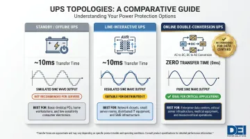
For any facility where even a 10 ms gap creates risk — financial services, healthcare, colocation — online double-conversion is the only viable choice.
Power Distribution Units (PDUs)
PDUs distribute power from the UPS to individual racks. Two categories define the market:
- Basic PDUs distribute power to rack equipment with no monitoring or remote management capability
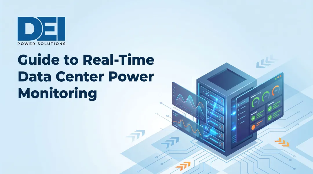
- Intelligent PDUs add real-time monitoring of current, voltage, power (kW), power factor, temperature, and humidity — plus remote outlet-level switching and DCIM integration
According to ASHRAE's data center power white paper, intelligent PDUs have become the norm because they enable load balancing, capacity planning, and PUE calculation. PDU selection must align with rack density and phase configuration — mismatched PDUs create phase imbalances that risk equipment damage and unplanned outages.
Remote Power Panels (RPPs)
When a PDU has power capacity but limited breaker space, RPPs extend distribution reach to rack clusters without adding upstream equipment. They enable flexible floor layouts and localized maintenance shutdowns without affecting the broader system.
DEI Power manufactures RPPs in five amperage ratings (225A, 400A, 600A, 800A, 1200A) with up to 84 branch circuits, designed specifically for hyperscale and enterprise data center deployments.
Backup Generators
Diesel or natural gas generators serve as the last line of defense during extended utility outages. Automatic transfer switches (ATS) detect utility failure and send start signals to generators, which must reach "Ready to Load" status within 4–8 seconds. NFPA 110 Type 10 systems require total transition within 10 seconds — while the UPS bridges this gap on battery power.
Generator sizing must account for the full IT load plus critical facility systems: cooling, fire suppression, and monitoring infrastructure. Undersized generators fail under full load, negating the entire backup strategy.
AC vs. DC Power and Single-Phase vs. Three-Phase
AC vs. DC Power
Most data centers receive AC power from the utility and distribute it throughout the facility. DC power appears primarily inside UPS systems (battery storage) and within server power supplies, where processors operate on DC. Some facilities experiment with end-to-end 380V DC or 800V DC distribution to reduce conversion losses. That said, AC-based architectures remain the standard — and the phase configuration within those AC systems is what most engineers focus on.
Single-Phase vs. Three-Phase Power
Single-phase power (two wires, 120/240V) suits small or residential loads. Three-phase power (three wires, 120° out of phase) is the standard for data centers because it delivers:
- More consistent power delivery with lower ripple
- Higher efficiency with reduced heat generation
- Better load distribution across conductors
Three-phase systems allow servers to draw from one or two phases per rack, making proper phase balancing critical. Unbalanced phases create neutral current, overheating, and equipment damage.
Typical voltage levels in data centers:
- 208/120V three-phase: Used for IT equipment distribution at the rack level
- 480/277V three-phase: Powers facility and mechanical loads, including UPS input
Phase balancing across racks directly affects system capacity and operating costs — imbalanced loads force neutral current that wastes energy and accelerates wear. PDU selection must match the facility's phase configuration from the start to avoid costly field corrections later.
Redundancy Strategies for Data Center Uptime
Redundancy is the engineering practice of adding backup capacity beyond what is strictly required to operate. In environments where downtime costs exceed $5,600 per minute, skipping redundancy isn't an option. It applies across the entire power chain: generators, UPS systems, switchboards, PDUs, and network feeds.
Common Redundancy Models
Three primary models define redundancy tiers:
- N: Exactly enough capacity to operate; no redundancy; single point of failure risk
- N+1: One additional component above minimum requirement; allows a single component to fail without interrupting operations
- 2N: Fully mirrored duplicate system with two independent power paths; tolerates both planned and unplanned events
Example: A data center requiring two generators to operate would run three under N+1 (two active, one standby) or four under 2N (two completely independent systems, each with two generators).
Uptime Institute Tier classifications map to redundancy strategies:
| Tier | Uptime | Max Annual Downtime | Redundancy | Characteristic |
|---|---|---|---|---|
| I | 99.671% | 28.8 hours | None (N) | Basic capacity |
| II | 99.741% | 22 hours | Partial | Redundant components |
| III | 99.982% | 1.6 hours | N+1 | Concurrently maintainable |
| IV | 99.995% | 26.3 minutes | 2N or 2N+1 | Fault tolerant |
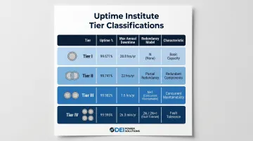
The tier your facility targets directly shapes how the power distribution system must be built. Design teams need to plan redundancy before the first panel goes in — retrofitting it into switchboards or distribution layouts that weren't engineered for it is rarely feasible. Bus configurations, panel layouts, and breaker allocations all need to account for future redundant feeds at the design stage.
What to Look for When Sourcing Power Distribution Equipment
Specification errors at the procurement stage cascade into field adjustments, inspection failures, and project delays. Contractors, engineers, and facility teams should evaluate equipment based on certifications, configuration accuracy, and manufacturing quality.
Certifications and Code Compliance
UL 891 certification ensures switchboards meet established safety standards required by most jurisdictions. This standard validates construction quality, fault current withstand ratings (typically up to 100 kAIC), thermal performance under load, and environmental exposure testing. Without UL listing, equipment creates liability and often fails inspection, requiring costly field corrections.
DEI Power manufactures UL 891-certified low-voltage switchboards built for high-uptime data center and industrial applications. Each unit uses genuine Siemens components and includes in-house engineering support to ensure correct configuration before shipment. Getting configuration right before shipment eliminates the change orders that field modifications generate.
Custom Configuration and Lead Times
Switchgear lead times now reach 40–60 weeks industry-wide, with transformers extending to 50–80 weeks. Overall data center project timelines have stretched from 12–18 months to 24–36 months, with utilities quoting 36–60 months for new power connections in some regions.
Off-the-shelf panels often require field modifications that increase costs and delay commissioning. Factory-configured equipment built to voltage, ampacity, and layout specifications eliminates these risks. DEI Power's in-house manufacturing enables custom switchboard builds in 4–6 weeks—significantly faster than standard industry timelines—while maintaining UL 891 compliance and exact specification matching.
For in-stock Remote Power Panels, DEI Power ships within 1 business day from their 50,000 sq. ft. Ontario, California facility, with delivery typically occurring within 3–5 business days nationwide.
Domestic Manufacturing and Documentation Quality
The Build America, Buy America Act (BABA) requires federally funded infrastructure projects to use domestically produced iron, steel, and manufactured products. For manufactured products, greater than 55% of total component cost must come from U.S.-sourced components. USA-manufactured equipment simplifies procurement for government-adjacent or compliance-sensitive projects.
Clear documentation directly reduces project risk. DEI Power provides:
- Accurate single-line diagrams and submittals with every order
- Configuration records that simplify inspection and commissioning
- Coordinated delivery planning to keep schedules on track
- 24/7 technical assistance from order through deployment
Frequently Asked Questions
How is power distributed in a data center?
Power flows sequentially from the utility grid through medium voltage switchgear, then steps down via transformers to low-voltage switchboards. From there, UPS systems provide battery backup and power conditioning before PDUs distribute power to individual server racks, with RPPs extending capacity to specific rack clusters.
How does a UPS system work in a data center?
A UPS sits between the low-voltage distribution layer and PDUs, using battery backup to supply instant power during outages with zero transfer time (in online double-conversion systems). It also conditions incoming power continuously to protect against voltage sags, surges, and electrical noise.
What is a PDU in a data center?
A PDU (Power Distribution Unit) distributes power from the UPS to individual server racks. Basic PDUs provide power only, while intelligent PDUs offer real-time monitoring of current, voltage, power, and environmental conditions, plus remote outlet switching and DCIM integration.
What is a remote power panel in a data center?
An RPP acts as a sub-panel extending distribution capacity from a PDU to specific rack clusters. It's valuable when a PDU has spare power capacity but no additional breaker space, enabling flexible floor layouts and localized maintenance shutdowns.
What kind of power do data centers need?
Data centers primarily use three-phase AC power for distribution efficiency, typically at 208/120V for IT equipment and 480V for facility systems. DC power supports UPS battery storage and server-level power conversion, though end-to-end DC architectures remain experimental.
Are switchgears used in data centers?
Yes. Switchgear controls, protects, and distributes power from the utility connection through to the UPS and PDU layers at both medium and low voltage levels. UL 891-listed low-voltage switchboards are the standard for mission-critical data center distribution.