Introduction
When IEC 61439 appears in U.S. project documentation, it tends to stop engineers and contractors cold. The standard is common in international work, but on domestic projects — where the Authority Having Jurisdiction expects UL-listed equipment — seeing an IEC reference raises real questions about procurement, code compliance, and project acceptance.
This guide answers those questions directly. You'll learn what IEC 61439 requires, why it replaced IEC 60439, and how the standard's multi-part structure works. More practically, you'll see how it compares to UL 891, UL 1558, and ANSI/IEEE C37.20.1 — the U.S. frameworks most North American projects actually require.
What Is Low-Voltage Switchgear and Controlgear?
Low-voltage switchgear and controlgear assemblies are factory-built enclosures containing combinations of switching devices (circuit breakers, contactors, disconnects), protective equipment, measurement instruments, and their interconnections. These assemblies distribute, protect, and control electrical power at voltages typically not exceeding 1,000V AC or 1,500V DC.
The term "switchgear and controlgear" describes two distinct but often integrated functions. Switchgear handles power switching and fault protection — opening circuits under normal and fault conditions alike. Controlgear manages electrical loads such as motors and process equipment. In practice, most low-voltage assemblies combine both functions within a single enclosure.
It's worth noting what IEC 61439 does and doesn't cover: individual components like circuit breakers and contactors fall under separate standards such as IEC 60947. IEC 61439 governs only the complete assembly.
Common deployment environments include:
- Industrial plants and manufacturing facilities
- Commercial buildings and campuses
- Utility substations and local power distribution networks
- Data centers where uptime is critical
- Healthcare facilities with uninterrupted power requirements
In these environments, reliability requirements make standardized design and verification essential. Without a verified assembly standard, failures carry consequences — unplanned downtime, safety incidents, and non-compliance — which is precisely why IEC 61439 exists.
What Is the IEC 61439 Standard?
A Replacement for IEC 60439
IEC 61439 replaced the older IEC 60439 standard, which had governed low-voltage switchgear assemblies for decades. The critical problem with IEC 60439 was its classification system: it distinguished between Type Tested Assemblies (TTAs) and Partially Type Tested Assemblies (PTTAs), but provided inadequate guidance on how PTTAs should be assessed for compliance.
This ambiguity led to inconsistent interpretations across manufacturers and testing bodies — some applied rigorous verification to modified designs, others took a more lenient approach. The result: uneven safety outcomes across the global market and real uncertainty for specifiers about what verification actually existed behind the equipment nameplate.
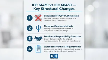
Key structural changes introduced by IEC 61439:
- Eliminated the TTA/PTTA distinction entirely, replacing it with a unified design verification framework
- Introduced three equivalent verification methods — testing, calculation/measurement, and design rules — that can be mixed across different assembly characteristics
- Formalized separate responsibilities for the Original Manufacturer (who verifies the reference design) and the Assembly Manufacturer (who builds specific units to that verified design)
- Expanded technical requirements in areas such as temperature rise, short-circuit withstand, environmental testing, and lifecycle performance
IEC 61439-1 Edition 1.0 was first published in 2009. The standard has undergone subsequent part-by-part revisions, with Edition 3.0 of Part 1 published in 2020 and Part 2 (Power Switchgear and Controlgear Assemblies) updated in July 2020. IEC 60439 was formally withdrawn on November 1, 2014, making IEC 61439 the only current standard for new equipment specifications.
Scope and Who IEC 61439 Applies To
Voltage and application scope: IEC 61439 applies to low-voltage switchgear and controlgear assemblies (LSCAs). These are enclosures — or groups of enclosures — containing switching, protection, measurement, control, and regulating equipment and their interconnections, covering assemblies rated up to 1,000V AC (50/60 Hz) or 1,500V DC.
Individual components such as circuit breakers and contactors are covered by separate IEC standards (notably IEC 60947), not IEC 61439. The standard addresses the complete assembly: how components are integrated, how they interact thermally and electrically, and how the finished unit performs under normal and fault conditions.
Two-party responsibility structure: One of IEC 61439's most important contributions is its clear distinction between two responsible parties:
Original Manufacturer's Obligations:
- Designs and verifies the reference assembly platform using one or more permitted methods (testing, calculation, design rules)
- Provides system documentation, type test results, and assembly instructions for downstream builders
Assembly Manufacturer's Obligations:
- Builds a specific assembly to the original manufacturer's verified design
- Confirms conformance through routine verification (inspection records, test results)
- Assumes full design verification responsibility for any deviations from the original design
Why this matters for procurement: When specifying IEC 61439-compliant equipment, confirm that both levels of responsibility are documented:
- The original manufacturer should provide design verification evidence — test reports, calculation records, or design rule documentation
- The assembly manufacturer should demonstrate routine verification showing the built unit matches the verified design
If an assembly manufacturer deviates from the original manufacturer's instructions — changing busbar sizes, altering compartment layouts, or substituting components — they assume responsibility for re-verifying those characteristics.
This shift in responsibility isn't always visible in procurement documents. Verify who performed design verification and whether the specific configuration you're purchasing has been verified before it ships.
The IEC 61439 Series: Parts and What They Cover
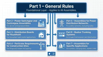
IEC 61439 is a multi-part standard where Part 1 (General Rules) establishes the foundational requirements referenced by all subsequent parts, and each subsequent part addresses a specific assembly type. Part 1 does not stand alone — it must always be used in conjunction with a product-specific part.
Key parts relevant to commercial and industrial applications:
| Part | Title | Application Scope |
|---|---|---|
| Part 1 | General Rules | Baseline standard; applies in conjunction with all other parts |
| Part 2 | Power Switchgear and Controlgear Assemblies (PSC) | Main power distribution assemblies for industrial and commercial facilities |
| Part 3 | Distribution Boards for Ordinary Persons (DBO) | Assemblies in residential and light commercial settings operated by non-skilled persons |
| Part 4 | Assemblies for Construction Sites (ACS) | Temporary power distribution on job sites |
| Part 5 | Assemblies for Power Distribution in Public Networks | Utility-level distribution assemblies |
| Part 6 | Busbar Trunking Systems (BTS) | Busway systems for distributing power through buildings or facilities |
| Part 7 | Assemblies for Specific Applications | Marinas, camping sites, EV charging, and other specialized environments |
For contractors and engineers on commercial, industrial, utility, or data center projects, Parts 1 and 2 are the most directly applicable. Part 6 also comes up frequently in large facilities that use busway systems to distribute power across floors or zones.
When a specification simply references "IEC 61439" without a part number, it typically invokes Parts 1 and 2 together, the combination that governs general-purpose power distribution assemblies. For specialized environments — construction sites, marinas, or public utility networks — confirm which specific part applies before proceeding.
Key Technical Requirements Under IEC 61439
Three Verification Methods
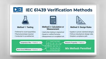
One of IEC 61439's most important contributions is the introduction of three equivalent verification methods that manufacturers can use to demonstrate compliance:
1. Verification by Testing Physical testing on a representative sample assembly under controlled laboratory conditions. This is the traditional "type test" approach where an assembly undergoes electrical, mechanical, and thermal testing to verify performance.
2. Verification by Calculation or Measurement Mathematical demonstration of compliance, such as calculating temperature rise using established formulas or comparing measured clearance and creepage distances against specified minimums. This method is permitted for certain characteristics within defined limits.
3. Verification by Design Rules Demonstrating compliance by comparison with an already-verified reference design, subject to strictly defined constraints. If the new assembly stays within specified parameters relative to the tested reference design, no separate testing or calculation is required.
A manufacturer may mix these methods across different characteristics within the same assembly. For example:
- Temperature rise: Verified by calculation (Method 2) for an 800A assembly based on a tested 1,600A reference design
- Short-circuit withstand: Verified by design rules (Method 3) because busbar dimensions and spacing match the reference design
- Dielectric properties: Verified by testing (Method 1) because insulation materials changed
This flexibility cuts cost and schedule time without compromising safety — but it demands clear documentation. Specifiers should ask which verification method applies to each characteristic and confirm that documentation supports each verification.
Temperature Rise Limits
Temperature rise verification prevents overheating, insulation degradation, and fire risk during continuous operation. IEC 61439 specifies maximum permissible temperature rises for terminals, busbars, and other components based on the material and accessibility.
Maximum permissible temperature rise values (key components):
- Terminals for external insulated conductors: 70 K
- Busbars and conductors (bare copper, maximum): 105 K
- Manual operating means (metal): 15 K
- Manual operating means (insulating material): 25 K
- Accessible external enclosures/covers (metal): 30 K
- Accessible external enclosures/covers (insulating): 40 K
Verification thresholds by rated current:
- Up to 630A: Verification by comparing installed power loss to the dissipatable power loss of the enclosure (permitted only with no horizontal partitions; derating factor of 0.8 applied)
- Up to 1,600A: Verification by calculation per IEC TR 60890 (technical report providing calculation methodology)
- Above 1,600A: Verification must be made by physical testing
For assemblies rated above 1,600A, manufacturers must conduct actual temperature rise testing or provide test data from a higher-rated reference design. Calculation alone is not sufficient.
Rated Diversity Factor (RDF): IEC 61439 introduces the Rated Diversity Factor: a per-unit value the manufacturer assigns to represent the percentage of rated current at which outgoing circuits can be continuously and simultaneously loaded.
In practice, not all circuits in an assembly operate at full rated current simultaneously. The RDF accounts for this, reducing total calculated heat generation below the theoretical maximum.
Beyond temperature rise, assemblies must also survive far more abrupt stresses — specifically, the mechanical and thermal forces that fault currents produce.
Short-Circuit Withstand Strength
Assemblies must demonstrate they can survive the mechanical and thermal stresses of fault currents without sustaining damage that would impair safety or function. Short-circuit withstand verification ensures that busbars, supports, compartments, and connections remain intact during fault conditions.
Verification by design rules (comparison with reference design): If specific parameters equal or exceed a tested reference design and other parameters equal or are less than the reference, no separate test or calculation is required. However, the comparison rules are tightly controlled. The following deviations from a tested reference design would require re-testing:
- Reductions in busbar cross-sections or changes in busbar profiles and spacing
- Changes to the type or quantity of busbar supports or support structures
- Exclusion of or changes to major short-circuit protective devices (SCPD)
- Reductions in compartment sizes
- Any configuration where the derived short-circuit rating would exceed that of the tested reference design
Exemptions from short-circuit verification: Short-circuit withstand verification is NOT required for:
- Assemblies with rated short-time withstand current (Icw) or rated conditional short-circuit current (Icc) not exceeding 10 kA effective value
- Assemblies protected by current-limiting devices with cut-off current not exceeding 17 kA
- Auxiliary circuits connected to transformers rated 10 kVA or less (secondary voltage ≥110 V) or 1.6 kVA or less (secondary voltage <110 V), provided short-circuit impedance is ≥4%
Unprotected live conductors: Maximum 3 meters between main busbars and the associated SCPD. Conductors must be arranged so a short circuit is a "remote possibility." Bare conductors must avoid mutual contact; 90°C insulated conductors must be loaded such that 80% of maximum operating temperature is not exceeded.
With short-circuit requirements established, the standard turns to insulation integrity, environmental protection, and long-term durability.
Dielectric Properties, IP Protection, and Additional Tests
Dielectric testing: Two tests verify insulation integrity under overvoltage conditions:
- Power-frequency withstand voltage: Test voltages range from 1,000V AC (for Ui up to 60V) to 1,890V AC (for Ui 300-690V), applied for 1 second
- Impulse voltage withstand test (Uimp): Rated impulse withstand voltage must equal or exceed specified transient overvoltages of the electrical system
IP protection (per IEC 60529): Degree of protection ratings confirm the enclosure prevents ingress of solids and water:
- Minimum indoor: IP2X (protection against fingers and objects >12.5 mm)
- Minimum outdoor: IPX1 (protection against vertically falling water)
- Assemblies for ordinary persons: at least IP2XC (protection against access to hazardous parts with a wire)
EMC requirements: IEC 61439 addresses electromagnetic compatibility for assemblies containing electronic devices. The standard defines two deployment environments:
- Environment A: Industrial low-voltage networks with strong interference sources
- Environment B: Public low-voltage networks serving domestic, commercial, and light industrial premises
If components comply with their own EMC standards (e.g., IEC 60947) and are installed per manufacturer instructions, no further assembly-level EMC testing is generally required.
Additional lifecycle and environmental tests: IEC 61439 introduced comprehensive testing to verify assembly performance across the full lifecycle:
- Corrosion resistance: Damp heat cycling and salt mist tests (Severity A for indoor, Severity B for outdoor)
- Glow wire testing: 960°C (parts retaining current-carrying parts), 850°C (enclosures for hollow walls), 650°C (all other parts)
- UV radiation resistance: Outdoor plastic/coated metal enclosures must retain ≥70% of flexural/impact strength per ISO 4892
- Lifting test: 1.25 times maximum transport weight, verifying structural integrity during transport and installation
- Marking legibility: Markings must remain legible after rubbing by hand for 15 seconds with water and 15 seconds with petroleum spirit
- Mechanical operation: Verified for 200 operating cycles
- Protective circuit continuity: Resistance must not exceed 0.1 ohm (tested at ≥10 A)
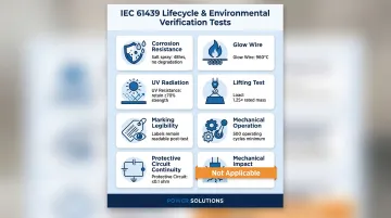
Important note on mechanical impact testing: Mechanical impact testing (IK code per IEC 62262) is NOT applicable to Power Switchgear and Controlgear Assemblies (PSC) under IEC 61439-2. If a specification requires IK ratings for PSC assemblies, this represents a misapplication of the standard — IK testing applies to distribution boards for ordinary persons (Part 3) and certain other assembly types, not PSC equipment.
IEC 61439 vs. U.S. Standards: What Engineers Need to Know
The fundamental framework difference between IEC 61439 and the U.S. system creates practical barriers that cannot be overcome through paperwork alone. IEC 61439 is the internationally dominant standard for low-voltage switchgear assemblies used across Europe, the Middle East, Asia-Pacific, and most international markets. The North American market operates under a parallel but distinct framework governed by UL and ANSI/IEEE standards.
Critical fact: IEC 61439-compliant equipment will not automatically satisfy NEC requirements or receive approval from U.S. Authorities Having Jurisdiction (AHJs). Per IEEE PCIC research, if equipment was designed only to meet IEC 61439-2 requirements, "it may not be able to be approved for use in the United States" without evaluation by an OSHA-recognized NRTL against applicable UL standards. This is not a minor documentation issue — it reflects structural differences in design requirements.
IEC-to-U.S. Standard Mapping
| IEC Standard | Approximate U.S. Equivalent | Key Application |
|---|---|---|
| IEC 61439-2 (PSC) — higher capacity | UL 1558 + ANSI/IEEE C37.20.1 | Primary distribution at service entrances or transformer secondaries |
| IEC 61439-2 (PSC) — secondary distribution | UL 891 | Secondary distribution downstream of main switchgear |
UL 1558 vs. UL 891: Key Differences Within the U.S. System
UL 1558 (Metal-Enclosed Low-Voltage Power Circuit Breaker Switchgear):
- Governs metal-enclosed power circuit breaker switchgear using draw-out frame breakers
- Provides higher short-circuit withstand ratings (minimum 4-cycle withstand at 60 Hz)
- Features full compartmentalization (separate bus, breaker, and cable compartments)
- Offers advanced arc-flash safety options through compartmentalized design
- Used for primary distribution at service entrances or transformer secondaries
- Continuous current ratings: 1,600A to 10,000A
- Maximum voltage: 600V AC
UL 891 (Switchboards):
- Governs switchboards with dead-front construction using fixed or plug-in MCCBs
- Typically front-accessible with a smaller footprint than UL 1558 equipment
- Serves secondary distribution downstream of main switchgear
- Generally less expensive than UL 1558 switchgear but offers fewer arc-flash safety options
- Used for distributing power to branch circuits and panel feeders
ANSI/IEEE C37.20.1-2015: The primary ANSI standard for metal-enclosed low-voltage power circuit breaker switchgear in North America, typically used alongside UL 1558. Defines construction, compartmentalization, and breaker derating rules for switchgear assemblies.
Critical Technical Differences: Why IEC Equipment Often Cannot Pass UL Evaluation
1. Clearance and Spacing Requirements: The IEEE PCIC paper identifies a critical spacing gap: IEC 61439-1 permits through-air spacing of 8 mm for an 8 kV impulse voltage rating, whereas equivalent UL standards require 25.4 mm through-air and 50.8 mm over-surface — a difference of more than 3x.
An assembly physically designed to IEC minimum clearances cannot pass UL evaluation without hardware redesign. The spacing difference is a hard physical barrier — not a documentation problem.
2. Short-Circuit Testing Rigor: UL 1558 requires AC switchgear to withstand short-circuit conditions for a minimum of four cycles (60 Hz basis) with specific power-factor conditions (15% lagging or less). IEC 61439 permits verification by comparison with a reference design or by design rules under certain conditions, providing more flexibility but potentially less prescriptive rigor than the mandatory UL testing regime.
3. Verification Philosophy: IEC 61439 employs a flexible three-method verification model (testing, calculation, design rules) across 12 characteristics. U.S. standards follow a prescriptive, test-centric model where specific tests are mandatory for specific product categories. This means IEC-designed assemblies may have design verification documentation that has no direct equivalent in the UL framework, and vice versa.
What This Means for U.S. Projects
For contractors and engineers specifying power distribution equipment on U.S. projects, compliance with the applicable UL standard — not just IEC 61439 — is non-negotiable for NEC compliance and project acceptance. Two NEC articles make this explicit:
- NEC Article 110.2: Equipment must be "acceptable only if approved"
- NEC Article 110.3(C): Products must be tested by a recognized testing laboratory — in practice, UL listing or approval by another OSHA-recognized NRTL
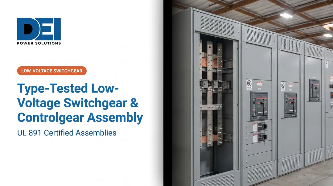
DEI Power manufactures UL 891-certified switchboards at a 50,000 sq. ft. facility in Ontario, California, using genuine Siemens components with in-house engineering support and lead times that ship most orders within 1 business day. Every unit carries Build America Buy America (BABA) compliance — domestic content certification for government projects and the AHJ documentation contractors need at submission.
Frequently Asked Questions
What is the IEC standard for low-voltage switchgear?
IEC 61439 is the primary international standard for low-voltage switchgear and controlgear assemblies, covering design verification, testing, and performance requirements up to 1,000V AC / 1,500V DC. It is widely adopted across Europe, the Middle East, Asia-Pacific, and Australia/New Zealand.
What is the difference between IEC 60439 and 61439?
IEC 60439 was the predecessor standard that distinguished between Type Tested Assemblies (TTAs) and Partially Type Tested Assemblies (PTTAs), causing inconsistent compliance enforcement. IEC 61439 replaced it in 2009 (with IEC 60439 withdrawn November 1, 2014) by eliminating that distinction, introducing three equivalent verification methods (testing, calculation, design rules), and clarifying the separate roles of Original Manufacturer and Assembly Manufacturer.
Is IEC 61439 mandatory?
In most IEC-adopting countries (EU, Middle East, Asia-Pacific), compliance is effectively required for legal sale and installation of low-voltage assemblies. In the U.S., UL and ANSI/IEEE standards govern instead — IEC 61439 compliance alone does not satisfy NEC requirements or AHJ approval.
What is the ANSI standard for low-voltage switchgear?
ANSI/IEEE C37.20.1-2015 is the primary standard for metal-enclosed low-voltage power circuit breaker switchgear in North America, defining construction, compartmentalization, and breaker derating rules — typically applied alongside UL 1558. Switchboards fall under UL 891; panelboards under UL 67.
What is the difference between UL 1558 and UL 891?
UL 1558 covers primary distribution switchgear with draw-out breakers, full compartmentalization, and high short-circuit ratings. UL 891 covers secondary distribution switchboards with fixed or plug-in MCCBs, a smaller footprint, and lower cost — though with fewer arc-flash safety options than UL 1558.
What is low-voltage switchgear and controlgear?
Low-voltage switchgear and controlgear assemblies are factory-built enclosures containing switching devices, protection equipment, and controls for systems up to 1,000V AC or 1,500V DC. They distribute, protect, isolate, and control electrical power across industrial, commercial, and utility applications.