Introduction
A 1000A, 480V service installation is a large-scale, three-phase commercial or industrial electrical system requiring licensed electricians, licensed engineers (PE stamp often required), utility coordination, and strict NEC compliance. This is not a DIY or general-trades task.
Three roles must work in coordination: licensed master electricians with industrial experience handle physical installation, electrical engineers provide system design and the required PE stamp, and utility representatives define the point of delivery. A gap in any one of them creates cascading risk downstream.
Poor execution has real consequences:
- Undersized conductors cause thermal failures
- Missing GFPE creates hidden equipment damage
- Improper termination torque leads to arc flash events
- Utility rejection delays energization by weeks
12% of all non-home fires involve electrical failure or malfunction, with 46% involving arcing. Every one of those failures is traceable to a skipped step.
Key Takeaways
- A 1000A, 480V service is a three-phase, solidly grounded wye system (277V to ground) used in heavy commercial, industrial, and data center environments
- NEC 230.95 mandates ground-fault protection of equipment (GFPE) on all 1000A+ disconnects on systems exceeding 150V to ground — non-negotiable on 480V systems
- Conductors at this ampacity almost always require parallel sets; sizing must account for the 1.25 continuous load rule under NEC 215.2
- Installation follows a strict sequence: utility coordination → permits and design → civil/structural prep → conduit and conductor installation → switchgear placement and termination → GFPE and metering → testing and inspection
- Skipping validation steps — torque checks, megger testing, GFPE functional test — creates failures that may not surface until equipment is damaged
Installation Guide for 1000 Amp 480V Service
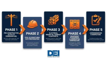
This installation spans five sequential phases — each with dependencies that must be completed before the next begins:
- Pre-construction coordination and utility approval
- Civil and structural site preparation
- Electrical rough-in (conduit and supports)
- Equipment placement and conductor termination
- Commissioning and inspection
Set clear expectations: a well-resourced project team may complete installation in several weeks, but utility coordination alone can extend timelines significantly. Skilled industrial electricians and an engineer of record are required at minimum.
Prerequisites and Safety Considerations
Utility coordination comes first. Confirm transformer capacity and point of delivery with the local utility provider before any design is finalized. Utilities may require their own engineering review and metering specifications that directly affect equipment selection.
Design and permitting requirements:
- A licensed PE must stamp the single-line diagram
- Local AHJ (Authority Having Jurisdiction) permits are required
- Most jurisdictions require a short-circuit current rating (SCCR) study and arc flash hazard analysis before installation begins
Site readiness checklist:
Confirm the equipment room or pad location meets NEC 110.26 working clearance requirements:
| Condition | Description | Minimum Depth |
|---|---|---|
| Condition 1 | Exposed live parts on one side; no live or grounded parts on other side | 3 ft |
| Condition 2 | Exposed live parts on one side; grounded parts on other side (concrete walls are grounded) | 3 ft 6 in. |
| Condition 3 | Exposed live parts on both sides of the work space | 4 ft |
Additional requirements:
- Minimum width of 30 in. or width of equipment (whichever is greater)
- Minimum height of 6 ft 6 in. or height of equipment (whichever is greater)
- Equipment doors must open at least 90 degrees
- Floor or pad must be rated for equipment weight
- Space must be protected from moisture and environmental hazards
Do not begin conductor pulls or equipment installation without:
- An approved permit
- A confirmed utility point of delivery
- A completed arc flash study
Starting without any of these three items risks failed inspections, equipment damage, and costly rework — in that order of likelihood.
Tools and Components Required
Key equipment:
- 1000A-rated service entrance switchboard or switchgear (UL 891 certified)
- Integral or external GFPE relay meeting NEC 230.95
- Revenue-grade metering as required by the utility
- Grounding electrode system sized to NEC 250.66
Conductor and conduit materials:
- Parallel sets of appropriately sized copper or aluminum THHN/THWN-2 conductors
- Large-diameter rigid metal conduit (RMC) or intermediate metal conduit (IMC) per fill calculations
- Compression-type lugs and connectors rated for the conductor size
Per NEC Table 310.16, typical conductor sizing for 1000A service (75°C rating, copper THHN):
| Conductor Size | Ampacity per Conductor | Parallel Sets Needed | Total Ampacity |
|---|---|---|---|
| 500 kcmil | 380A | 3 sets | 1,140A |
| 600 kcmil | 420A | 3 sets | 1,260A |
Sizing must account for the 1.25 continuous load multiplier under NEC 215.2.
Pulling and terminating conductors at this scale also requires specialized tools:
- Hydraulic cable puller for large kcmil conductors
- Calibrated torque wrench matched to lug manufacturer specifications
- Insulation resistance tester (megohmmeter)
- Digital clamp meter for load verification
- Personal arc flash PPE rated to the incident energy level from the arc flash study
How to Install: Step-by-Step
Installation of a 1000A, 480V service must follow a defined sequence. Energizing equipment before testing is complete is one of the most common causes of both equipment damage and failed inspections — don't skip ahead.
Step 1: Finalize design and pull permits
- Confirm the single-line diagram is PE-stamped and AHJ-approved
- Execute the utility interconnection agreement
- Review and approve all material submittals (switchgear, conduit, conductor specs) before ordering long-lead equipment
Step 2: Prepare the installation site
- Pour or verify the concrete equipment pad
- Install seismic anchoring if required by local code
- Ensure the room is enclosed, ventilated, and lit per NEC 110.26(D)
- Install cable tray or conduit supports prior to pulling wire
Step 3: Install conduit runs and pull parallel conductor sets
- Install conduit runs from the utility point of entry to the main switchgear location
- Pull parallel conductor sets per phase
- Ensure each parallel set is of equal length and conductor size to share current evenly
- Label all conductors at both termination points before pulling
NEC Annex C Table C.1 sets the following minimum conduit sizing for parallel sets:
| Conductor Size | Conductors per Set | Minimum RMC Trade Size |
|---|---|---|
| 500 kcmil THHN | 3 | 3 in. |
| 600 kcmil THHN | 3 | 3 in. (tight fit; consider 3.5 in.) |
Step 4: Set and anchor the main service entrance switchgear
- Position the switchboard or switchgear on the pad using proper lifting equipment
- Anchor to the pad per manufacturer instructions and seismic requirements
- Verify plumb and level
- Confirm all internal bus connections are factory-torqued before opening the enclosure for field wiring
Step 5: Terminate conductors, install grounding system, and connect GFPE
- Terminate all phase, neutral, and ground conductors using manufacturer-specified torque values (record each value)
- Install the grounding electrode system including ground rods, building steel, and water pipe connections per NEC 250.50
- Wire and set the GFPE relay trip threshold per NEC 230.95 (maximum 1,200A pickup, maximum 1-second time delay)
Per NEC Table 250.66, grounding electrode conductor sizing for 500-600 kcmil copper service conductors: 1/0 AWG copper GEC.
NEC Table 250.122 sets the equipment grounding conductor for a 1000A overcurrent device at 2/0 AWG copper EGC.
Post-Installation Checks and Validation
Before requesting utility energization:
Perform insulation resistance (megger) testing on all conductors to verify no insulation damage occurred during the pull. Per NETA ATS-2017 standards, test values for cables rated 600V:
- Test voltage: 500-600 VDC
- Minimum acceptable insulation resistance: 100 megohms (based on 1,000 ft of cable at 60°F conductor insulation temperature)
- Absolute minimum without correction factors: 2 megohms
- Test duration: at least 60 seconds with measured resistance stabilizing
Document test results — they are required for inspection.
GFPE functional test:
NEC 230.95(C) requires that the GFPE system be tested when first installed using a primary injection test method. Confirm the relay trips within the set time delay at the set current threshold, and retain the test report for the AHJ.
After initial energization:
Conduct a thermographic (infrared) scan of all terminations and bus connections under load to identify any hot spots caused by improper torque or poor contact. NFPA 70B 2023 elevated thermographic inspection to a mandatory requirement for all electrical equipment, with inspections required at least every 12 months. In practice, skipped thermographic scans are a leading cause of connection failures within the first year of service — loose or undertorqued terminations that pass visual inspection will show up clearly under infrared.
Common Installation Problems and Fixes
Undersized Conductors Due to Ignoring the Continuous Load Rule
Problem: Conductors are sized to match the 1000A breaker rating exactly, but the actual load is continuous (operating 3 hours or more), causing conductors to run at the thermal limit and overheat over time.
Likely cause: The NEC 1.25 continuous load multiplier (NEC 215.2) was not applied during design. A 1000A continuous load requires conductors and overcurrent protection sized to at least 1,250A ampacity.
High-level fix: Revisit the load calculations during design review before conductors are purchased. If conductors are already installed, a licensed engineer must evaluate whether parallel sets need to be added or replaced.
Missing or Improperly Configured GFPE
Problem: The switchgear is installed and energized but the GFPE relay is not set correctly, not tested, or not present. This violates NEC 230.95 and allows low-level ground faults to damage equipment undetected over time.
Likely cause: GFPE is treated as an afterthought or the installer is unfamiliar with NEC 230.95 requirements specific to 480V systems exceeding 150V to ground.
High-level fix:
- Verify GFPE is specified in the switchgear order before fabrication
- Confirm relay settings and conduct the required primary injection test before the AHJ inspection
- Do not energize permanently until the test is documented
Termination Failures from Improper Torque
Problem: Connections at switchgear lugs or conductor terminations are under- or over-torqued, causing resistance heating at the connection point. This typically presents as a hot spot in an IR scan or, in the worst cases, a termination failure under load.
Likely cause: Torque specifications from the lug or busbar manufacturer were not followed, or a calibrated torque wrench was not used. According to a ResearchGate study on electrical system failures, approximately 20–25% of total failures stem from poor terminations and loose connections.
High-level fix: Re-torque all terminations to manufacturer specifications using a calibrated torque wrench. Document all torque values as part of the project closeout package. Schedule an IR scan within the first 30-90 days of operation.
Pro Tips for Installing a 1000A 480V Service Effectively
Start utility coordination first. Transformer sizing, point-of-delivery approval, and metering requirements can add months to a project if initiated late — this is the most common cause of schedule overruns on large service installations.
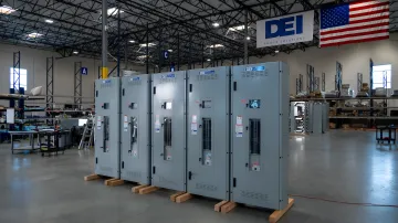
Specify pre-engineered, UL 891-certified switchgear over field-assembled solutions. Factory-built switchboards ship with tested bus connections, documented SCCR ratings, and pre-wired GFPE provisions that reduce field errors and inspection risk. DEI Power's custom-built 1000A switchboards are configured to your voltage, layout, and jobsite specs with in-house engineering support — helping contractors cut change orders and rework before they start.
Maintain a formal documentation package throughout installation. Record all torque values, megger test results, GFPE test data, and conductor routing as-builts. AHJs require this package for sign-off, and it becomes essential when troubleshooting issues years later.
Conclusion
A 1000A, 480V service installation is a high-stakes, multi-discipline project where errors in sizing, grounding, GFPE configuration, or termination quality can result in equipment damage, failed inspections, arc flash events, or prolonged downtime. A single miscalculation at any phase can cascade into costly delays, failed commissioning, or dangerous field conditions.
Treat every phase as non-negotiable:
- Design: Size conductors, overcurrent protection, and grounding to NEC 230 and 250 requirements — no shortcuts
- Execution: Use licensed electricians with demonstrated experience on commercial or industrial 480V systems
- Termination: Torque all lugs to manufacturer spec and document with a calibrated tool
- GFPE: Configure and test ground fault protection before energization, not after
- Commissioning: Validate metering, protection settings, and arc flash labeling before handoff
For mission-critical facilities — data centers, healthcare, industrial plants — sourcing pre-engineered, UL 891-certified switchgear significantly reduces field complexity and schedule risk. DEI Power manufactures in-stock, BABA-compliant switchboards from 400A to 4000A out of their 50,000 sq. ft. facility in Ontario, California, with lead times that keep projects moving when time matters most.
Frequently Asked Questions
What size wire do you need for 1000 amps?
Per NEC Table 310.16, 500 kcmil copper THHN at 75°C is rated at 380A per conductor, so three parallel sets yield 1,140A total. Final sizing depends on conduit fill, temperature rating, and whether the load is continuous (the 1.25 multiplier applies).
What size ground for 1000 amp service?
Per NEC Table 250.66, the grounding electrode conductor for 500–600 kcmil copper service conductors is 1/0 AWG copper. Per NEC Table 250.122, the equipment grounding conductor for a 1000A overcurrent device is 2/0 AWG copper.
How many conductors for 480V?
A 480V three-phase service uses three phase conductors, a neutral (for 4-wire 277/480V wye systems), and a grounding conductor. At 1000A, each phase requires multiple parallel sets per NEC 310.10(H), such as three sets of 500 kcmil copper.
What is the 1.25 rule in electrical?
NEC 210.20 and 215.2 require conductors and overcurrent devices serving continuous loads (loads expected to run 3 or more hours) to be sized at 125% of the continuous load current. A 1000A continuous load requires equipment rated at a minimum of 1,250A.
Does a 1000 amp 480V service require ground-fault protection of equipment (GFPE)?
Yes. NEC 230.95 requires GFPE on service disconnects rated 1000A or more on solidly grounded wye systems exceeding 150V to ground. A 480V system has 277V to ground, which triggers this requirement. The GFPE must be tested upon installation per NEC 230.95(C).
What conduit size is needed for 1000 amp service conductors?
Conduit size depends on conductor count and size. Per NEC Annex C, three sets of 500 kcmil THHN require minimum 3 in. RMC per parallel set; step up to 3.5 in. when pulling 600 kcmil for easier installation.