Introduction
A 1000 amp 240V single-phase service installation is a technically demanding, high-stakes project requiring careful planning, licensed expertise, and strict regulatory compliance. At this ampacity, every detail matters — from parallel conductor sizing to switchboard short-circuit current ratings (SCCR) — because errors can create serious arc-flash hazards, costly inspection failures, and dangerous equipment malfunctions.
NEC 110.9 requires equipment to have an interrupting rating equal to or exceeding the available fault current at its terminals. Equipment rated below that threshold risks "meltdown, explosion, or similar catastrophe" during fault events.
This installation involves four coordinated requirements: confirming available fault current with the utility, meeting NEC Article 230 service entrance rules, sizing parallel conductor sets per NEC 310.10(H), and installing UL 891-listed switchgear rated for the full fault current.
Only licensed master electricians and electrical engineers familiar with large commercial and industrial service entrances should perform this work. AHJ permits and utility pre-approval are non-negotiable prerequisites before any work begins.
This guide covers the complete installation process — conductor sizing, switchboard placement, grounding, and commissioning — following NEC standards and best-practice sequencing.
Key Takeaways
- Licensed electricians, engineering sign-off, and utility coordination are required before work begins
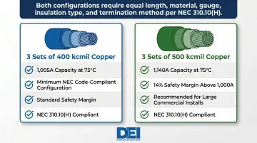
- Conductors run in parallel sets per NEC 310.10(H) — typically three sets of 400 kcmil copper minimum
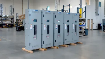
- The main service disconnect must be a UL 891-listed switchboard rated for available fault current (SCCR)
- Post-installation testing requires insulation resistance verification and torque confirmation per spec
- Skipping utility approval or AHJ permitting will result in refused energization and costly delays
Installation Guide for a 1000 Amp 240V Single-Phase Service
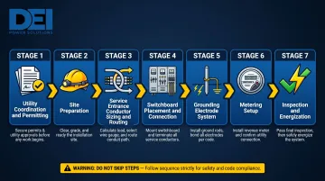
The installation follows a strict sequence: utility coordination and permitting → site preparation → service entrance conductor sizing and routing → switchboard placement and connection → grounding electrode system installation → metering setup → inspection and energization. Deviating from this sequence, especially energizing before inspection, creates serious safety and compliance risk.
Expect a multi-day project requiring a licensed electrical team, structural assessment of the service entrance location, and advance ordering of long-lead components. Switchgear, meter sockets, and large-format conductors often have lead times of 30-50 weeks (compared to pre-pandemic 8-12 weeks), so factor this into your schedule.
Prerequisites and Safety Considerations
Before installation begins, confirm these non-negotiables:
Utility Pre-Approval:
- Serving utility must approve service size and confirm available fault current (short circuit current)
- Obtain written documentation of available fault current for equipment SCCR matching
- Verify utility metering requirements (CT cabinet specifications above 400A single-phase)
- Confirm transformer capacity can support 1000A load (240,000 watts at 240V)
AHJ Permit and Plans:
- Submit permit application with approved electrical plans before any installation work
- Include service entrance conductor sizing calculations per NEC 310.15 and 310.10(H)
- Provide switchboard specifications showing SCCR rating and UL 891 listing
- Document grounding electrode system design per NEC Article 250
Structural and Spatial Readiness:
- Verify service entrance location meets NEC 110.26 working clearance requirements: minimum 36 inches depth, 30 inches width, and 6.5 feet height in front of switchboard
- Confirm floor structure can support 300+ pound switchboard weight
- Ensure conduit entry points align with switchboard internal bus and termination locations per NEC 230.70
Technical Compatibility:
- Confirm utility voltage is true 240V single-phase (center-tapped transformer secondary delivering two 120V legs and neutral)
- Obtain written available fault current rating at service point
- Match switchboard SCCR to meet or exceed available fault current (NEC 110.9 and 408.6)
Critical Safety Requirements:
- Do not proceed without utility written approval
- Do not install unlisted or field-modified switchgear
- Do not use undersized parallel conductor sets violating NEC 310.10(H)
- Personal protective equipment (PPE) rated for arc-flash hazard level is required throughout
Tools and Parts Required
Major Components Checklist:
- Service entrance conductors: Three parallel sets of 400 kcmil copper THHN/THWN-2 (minimum code-compliant configuration yielding 1,005A at 75°C) or three sets of 500 kcmil copper (1,140A) for 14% safety margin
- Conduit: Sized per NEC Chapter 9 fill calculations for parallel conductor sets
- 1000A main service disconnect/switchboard: UL 891-listed, rated for available fault current, with SCCR documentation
- Meter socket or CT cabinet: Per utility specifications (CT metering required above 400A single-phase)
- Grounding electrode conductors and electrodes: Per NEC Article 250 (minimum 2/0 AWG copper for service conductor equivalent area of 1,500 kcmil)
- Calibrated torque tools: All connections at 1000A must be torqued to manufacturer specifications
Specialist Tools and Equipment:
- Large-format conductor pulling equipment (tuggers, sheaves)
- Hydraulic crimping tools for large lug terminations
- Calibrated torque wrenches
- Insulation resistance tester (megohmmeter) for pre-energization testing
Lead Time Considerations:
The switchboard is typically the longest-lead item. Generic switchgear requiring field modification commonly runs 30-50 weeks. DEI Power's UL 891-certified switchboards, built to order in Ontario, California, ship in 4-6 weeks — a meaningful difference on time-sensitive projects.
How to Install a 1000 Amp 240V Single-Phase Service (Step-by-Step)
Steps must be executed in order. Skipping or compressing steps, especially pre-energization checks, is the most common source of failures and inspection rejections.
Step 1 — Prepare the Service Entrance Location
- Confirm working clearances per NEC 110.26: minimum 36 inches depth, 30 inches width, 6.5 feet height
- Mount conduit entry points and weatherhead (or underground conduit stub-up)
- Install switchboard mounting structure and verify surface can support equipment weight
- Ensure location is readily accessible per NEC 230.70(A) and not in a bathroom
Step 2 — Install Service Entrance Conduit and Pull Conductors
With the entrance location prepared, conduit runs and conductor pulls can begin.
- Install conduit runs from utility connection point to switchboard
- Size conduit for parallel conductor sets with appropriate fill percentages per NEC Chapter 9
- Pull conductors in parallel sets simultaneously where possible to prevent damage
- Leave adequate tail length at both utility termination point and switchboard
- Ensure all parallel conductors meet NEC 310.10(H): same length, same material (all copper or all aluminum), same circular mil area, same insulation type, same termination method
Step 3 — Set and Secure the 1000A Switchboard
- Position switchboard in prepared location and anchor per manufacturer specifications
- Verify conduit entries align with internal bus and termination locations
- Ensure switchboard is level and fully secured before beginning wiring
- Confirm SCCR rating on equipment nameplate matches or exceeds utility's available fault current
Step 4 — Terminate Conductors and Connect Grounding Electrode System
This is the highest-consequence step. Every connection must be torqued and documented before moving forward.
- Torque all lugs and bus connections to manufacturer's specified values (under-torqued connections at 1000A cause connection failures and fires)
- Install grounding electrode system per NEC 250.50: all required electrodes (ground rods, concrete-encased electrode if applicable, water pipe ground) bonded together
- Bond neutral and ground at service point only per NEC 250.28 (main bonding jumper)
- Size grounding electrode conductor per NEC Table 250.66 (minimum 2/0 AWG copper for 1,500 kcmil equivalent service conductor area)
- Seal all conduit entries per NEC 230.8 to prevent gases from entering switchboard
Step 5 — Coordinate Utility Metering Installation
- Verify CT cabinet or meter socket is installed, wired, and accepted per utility specification
- Obtain metering acceptance in writing before scheduling final inspection
- Utility installs revenue meter after contractor-provided cabinet is approved
Post-Installation Checks and Validation
Before requesting energization, perform these critical checks:
Visual Inspection:
- Verify all conductors landed on correct terminals
- Confirm all torque marks are in place and documented
- Ensure all conduit entries sealed per NEC 230.8
- Check all labeling complete per NEC 230.70 and manufacturer requirements
Insulation Resistance Testing:
Perform megohmmeter testing on all service entrance conductors before energization:
- Per NETA ATS-2017 Table 100.1, minimum acceptable insulation resistance for 600V-class equipment is 100 megohms at 1,000 VDC test voltage
- A reading below this threshold indicates damaged insulation that must be corrected before proceeding
Grounding System Verification:
- Verify continuity of grounding electrode system
- Confirm main bonding jumper installed only at service disconnecting means
- Check no neutral-to-ground bonds exist at downstream panels
AHJ Final Inspection:
The AHJ must complete a final inspection before the utility will authorize energization. Inspectors typically check:
- Working clearances meet NEC 110.26
- Conductor sizing documentation and calculations
- Switchboard UL listing and SCCR rating
- Grounding compliance per NEC Article 250
- Complete labeling and arc-flash warning per NEC 110.16
Missing torque records or conductor sizing calculations will cause inspection failure. Keep documentation complete before scheduling the walkthrough.
Many connection and insulation issues only become apparent under load. A service that passes cursory visual inspection but was not properly megohmmed or torque-checked can fail within weeks of energization, requiring a complete shutdown to remediate.
Common Installation Problems and Fixes
These three problems come up repeatedly on 1,000A single-phase service installations — each one is avoidable with the right planning.
Undersized or Improperly Configured Parallel Conductor Sets
Problem: Conductors overheat or voltage drop is excessive at full load.
Likely Cause: Parallel sets not sized correctly per NEC 310.10(H), or sets pulled with mismatched lengths violating equal-impedance requirement.
Fix: Recalculate conductor sizing per NEC 310.15 for actual load and temperature rating. All parallel conductors in each phase must match on:
- Length (equal impedance required)
- Gauge and insulation type
- Raceway type
Minimum compliant configuration is three sets of 400 kcmil copper (1,005A at 75°C). Three sets of 500 kcmil copper (1,140A) provides a safer margin.
Switchboard SCCR Mismatch
Problem: AHJ or utility rejects switchboard because its short circuit current rating is lower than available fault current at service point.
Likely Cause: The installer didn't confirm available fault current with the utility before specifying equipment and assumed a default SCCR.
Fix: Obtain utility's written available fault current value before ordering switchgear. Specify switchboard whose SCCR meets or exceeds that value. Replacing an under-rated switchboard after installation is expensive and causes costly delays to your project schedule.
Grounding and Bonding Errors at the Service
Problem: Nuisance trips, equipment damage, or failed inspection due to incorrect neutral-to-ground bonding.
Likely Cause: Main bonding jumper installed in wrong location, or neutral bonded at subpanel location downstream of service.
Fix: Confirm per NEC 250.28 that main bonding jumper is only at service disconnecting means. Remove any neutral-to-ground bonds at downstream panels. Verify with licensed electrician before energization.
Pro Tips for Installing a 1000A 240V Single-Phase Service Effectively
Start Utility and AHJ Coordination Months Before Planned Installation
Large service installations often require utility infrastructure upgrades — transformer sizing, secondary conductor upgrades — with lead times of 30-50 weeks. Starting coordination late is the single most common cause of project delays.
Order Switchgear Early and Verify Configuration in Advance
A 1000A switchboard configured incorrectly for conduit entries, bus arrangement, or metering requirements causes costly field modifications. Factory-built, pre-engineered switchgear with full documentation support cuts that risk significantly — DEI Power's UL 891-certified, custom-configured switchboards ship with configuration documentation that reduces both field changes and AHJ rejections.
Maintain a Torque and Documentation Log Throughout Installation
AHJ inspectors at this scale often require evidence of torque compliance, not just visual inspection. Log torque values at each termination during installation — this prevents re-inspection delays and creates a permanent maintenance record for the facility.
Conclusion
A 1000A 240V single-phase service installation demands a disciplined, sequenced approach. At this scale, errors are expensive to fix and create serious safety hazards. Before energization, every phase of the work needs to be right:
- Utility coordination and permitting completed before site work begins
- Parallel conductors configured per NEC 310.10(H) with matched impedance
- UL 891 switchgear rated for available fault current (SCCR verified)
- Grounding system validated before the service is energized
Teams should invest in pre-installation engineering review and source switchgear from suppliers who ship code-compliant, pre-configured assemblies with complete documentation. DEI Power manufactures UL 891-certified switchboards in-house at their Ontario, California facility — built to spec, ready to install, and backed by engineering support that reduces field uncertainty and change orders.
When the equipment arrives right and the planning is thorough, first-inspection approval is the expected outcome, not a lucky one.
Frequently Asked Questions
What wire size is required for a 1000 amp 240V single-phase service?
At 1000A, conductors must be run in parallel sets per NEC 310.10(H). Common configurations include three sets of 400 kcmil copper (1,005A at 75°C) or three sets of 500 kcmil copper (1,140A) for added margin. Exact sizing requires load calculations and temperature correction per NEC 310.15, confirmed by a licensed engineer.
What NEC code sections apply to a 1000 amp service installation?
Key articles include Article 230 (Services), Article 240 (Overcurrent Protection; 1000A is a standard rating per Table 240.6(A)), Article 250 (Grounding and Bonding), and NEC 310.10(H) (parallel conductors). NEC 110.9 covers interrupting ratings; NEC 110.26 specifies working clearances.
Does a 1000 amp single-phase service require utility coordination?
Yes, utility pre-approval is always required before installation begins. The utility must confirm available fault current, metering requirements (typically CT metering above 400A single-phase), and transformer capacity before the service can be designed and installed. Utilities require written approval before work begins.
Can you run 240V on a 100 amp service?
Yes, 240V can be supplied by a 100A single-phase service, but total available power is limited to 24,000 watts at full load. A 100A service is appropriate for small residential or light commercial loads, while large commercial and industrial applications require significantly higher service ratings like 1000A.
How many amps is 1000 watts at 240 volts?
Using the formula Amps = Watts ÷ Volts, 1000W ÷ 240V = approximately 4.17 amps. A 1000A service at 240V can supply up to 240,000 watts (240 kW) of connected load, which is why this service size is reserved for large commercial and industrial facilities.
What is the difference between a 1000A switchboard and a panelboard at this service size?
A switchboard (governed by UL 891) is a large, floor-mounted assembly designed for high-ampacity service entrances and distribution, while a panelboard is a smaller, wall-mounted enclosure used downstream for branch circuit distribution. At 1000A, a UL 891-listed switchboard is the appropriate main service equipment due to required bus bracing, wiring space, SCCR ratings, and available fault current capacity.