This is not a single-trade task or a DIY project. Successfully bringing 480V service online requires a licensed electrical contractor working from stamped engineering drawings, full coordination with the serving utility, and strict compliance with NEC requirements verified by the authority having jurisdiction (AHJ). Every step—from load calculations and switchgear sizing to pre-energization testing and phase rotation verification—must be executed correctly before the system can be safely energized and commissioned.
Key Takeaways
- 480V three-phase is the standard for mid-to-large commercial buildings because it delivers power efficiently to high-demand motor loads and reduces conductor size
- The 480Y/277V Wye configuration dominates new construction — one service delivers 480V for three-phase equipment and 277V for lighting
- Installation success depends on utility coordination, NEC Article 220 load calculations, correct switchgear sizing, and code compliance before energization
- Three recurring failures to avoid: incorrect phase rotation (motors run backward), voltage imbalance from uneven load distribution, and undersized distribution equipment
- 480V is the distribution voltage; equipment is rated for 460V utilization, with an acceptable operating range of 414V–506V per ANSI C84.1
Why Commercial Buildings Use 480V Three-Phase Power
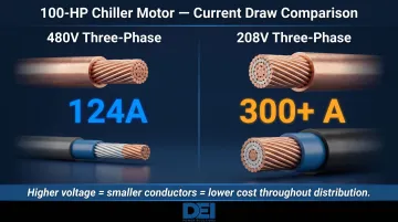
Commercial buildings choose 480V three-phase power for one fundamental reason: efficiency. At higher voltage, less current is required to deliver the same power (I = P/V), which allows smaller conductors to carry the load over longer distances inside a facility. This matters most in large commercial buildings where distribution runs span hundreds of feet from the service entrance to remote mechanical rooms, rooftop equipment, and basement electrical closets. Compared to 120/208V service found in smaller commercial spaces, 480V systems reduce I²R losses and lower total installed cost for conductor, conduit, and labor.
Key loads that require 480V three-phase in commercial buildings include:
- HVAC chillers and large air handlers
- Elevator motors and traction drives
- Commercial kitchen equipment (ovens, dishwashers, fryers)
- Large compressors and process equipment
- Data center UPS systems and power distribution units
- Motor control centers (MCCs) serving multiple process loads
These loads simply cannot be served efficiently at lower voltages. A 100-HP chiller motor, for example, draws approximately 124 amps at 480V three-phase but would require over 300 amps at 208V. That difference in conductor size cascades through every piece of distribution equipment from the service entrance to the motor starter.
460V vs. 480V: What's the Difference?
These terms refer to different points in the distribution system. 480V is the ANSI/IEEE standard distribution voltage supplied by the utility transformer secondary. 460V is the NEMA utilization voltage rating at the equipment terminals, after accounting for voltage drop along feeders and branch circuits. Per ANSI C84.1 voltage tolerance standards, the acceptable operating range at the equipment is ±10% of utilization voltage — roughly 414V to 506V. Equipment must tolerate this variation without performance degradation.
Understanding 480V Three-Phase Configurations: Wye vs. Delta
The two main three-phase wiring configurations—Wye (star) and Delta—determine what voltages are available in the building and what types of loads can be served. Most modern commercial buildings use the Wye configuration for its flexibility and efficiency in serving mixed loads.
Wye (480Y/277V) Configuration
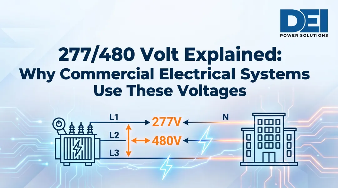
The 480Y/277V Wye configuration is the dominant choice for commercial buildings. In this system, three ungrounded conductors and one neutral are connected at a common neutral point at the utility transformer secondary. Phase-to-phase voltage measures 480V for three-phase motor loads, and phase-to-neutral voltage measures 277V for single-phase lighting circuits.
That dual-voltage capability has real practical value: the same service delivers 480V power to mechanical equipment and 277V power to fluorescent or LED lighting fixtures throughout the building, eliminating the need for a separate step-down transformer dedicated to lighting. ANSI C84.1 designates 480Y/277V as a preferred nominal system voltage for large commercial and industrial facilities for exactly this reason.
Phase conductor color coding (industry convention, not NEC mandate):
- Brown (L1)
- Orange (L2)
- Yellow (L3)
- Gray (neutral)
- Green or bare (equipment ground)
While NEC 210.5(C) and 215.12 require phase identification where more than one voltage system exists, the code does not mandate specific colors for ungrounded conductors. The Brown-Orange-Yellow convention is widely adopted but must be verified with the local AHJ and documented at distribution equipment per code requirements.
Delta Configuration
Where Wye's neutral point is its key advantage, the three-wire Delta configuration has none. It provides only line-to-line voltage at 480V, so Delta systems cannot serve single-phase 277V lighting loads without a separate step-down transformer.
This configuration is still found in older industrial facilities and applications requiring high motor starting torque, but it has largely been replaced by Wye systems in modern commercial construction due to its lack of flexibility for mixed loads.
High-leg delta at 480V: In a center-tapped delta, the "wild leg" or high leg measures approximately 416V to ground (calculated as 480V × 0.866). Per NEC 110.15 and 408.3(E), this conductor must be marked orange and identified at all terminations. High-leg delta at 480V is almost never used in commercial buildings. The 416V-to-ground hazard creates serious safety risks if the wild leg is mistakenly used for single-phase loads, and the configuration offers no practical benefit over 480Y/277V for mixed commercial loads.
Planning and Prerequisites Before 480V Service Installation
Before any 480V service installation work begins, the following must be confirmed to avoid downstream inspection failures and liability risks:
Critical prerequisites:
- Utility coordination to confirm transformer capacity, service entrance requirements, and point of common coupling
- Site electrical design drawings stamped by a licensed professional engineer
- Load calculations per NEC Article 220 that account for demand factors and future growth
- AHJ permit approval and approved plan review before equipment installation
Skipping any of these creates costly delays, rework during inspection, and potential liability if equipment fails or injures personnel.
Load Calculations and Service Sizing
Load calculations determine the size of the service entrance conductors, main disconnect, and distribution switchgear. Total connected load (the sum of all equipment nameplate ratings) is not the same as demand load (the actual maximum load the building will draw simultaneously). NEC Article 220 governs how demand factors are applied to arrive at the correct service entrance rating.
Getting that number wrong in either direction is expensive:
- Over-sizing wastes capital on larger transformers, switchgear, and conductors than the load requires
- Under-sizing forces costly service upgrades mid-project when tenants or equipment are added
The calculation must also include headroom for future expansion—typically 20-25% spare capacity above the initial demand load.
Service Entrance Equipment Specification
At the service entrance, the following equipment must be specified and installed:
- Main service disconnect (circuit breaker or fused switch)
- Metering equipment per utility requirements (meter socket, CT cabinet, or revenue-grade metering)
- Main switchboard or switchgear assembly that distributes power to downstream panelboards and motor control centers
UL 891-certified switchboards provide a pre-engineered, factory-assembled distribution point for 480V commercial service. These assemblies are tested to UL standards for temperature rise, dielectric strength, and short-circuit withstand, reducing field configuration errors and change orders compared to field-assembled equipment. DEI Power manufactures UL 891-certified switchboards in amperage ratings from 400A to 4000A using Siemens components, offering pre-engineered solutions that support faster project timelines and code compliance verification.
Non-negotiables before energization:
- Valid electrical permit and approved plan review
- Utility approval and scheduled energization date
- Completed arc flash risk assessment per NFPA 70E
Missing any one of these at the energization stage triggers utility holds, failed inspections, or—in the case of an arc flash assessment—direct NFPA 70E liability exposure for the project team.
How 480V Three-Phase Service Is Installed in Commercial Buildings
480V service installation follows a defined sequence from utility coordination through final commissioning. Skipping steps—especially utility coordination or pre-energization testing—is where most project delays originate.
Coordinating Utility Service and Transformer Setup
The serving utility delivers 480V three-phase service via a pad-mounted or vault transformer that steps down medium-voltage distribution (typically 12.47 kV or 13.8 kV) to 480Y/277V. The electrical contractor coordinates with the utility on service entrance conductor routing, metering location, and the point of common coupling where ownership transfers from the utility to the building owner.
Utility requirements vary significantly by region and must be confirmed early in design—some utilities require specific metering configurations, CT ratios, or equipment clearances that affect switchboard layout and site grading. Missing these details late in design can push back the transformer installation and the entire project energization date.
Installing the Service Entrance and Distribution Equipment
Physical installation proceeds in this sequence:
- Pull and terminate service entrance conductors from the utility transformer to the meter socket
- Install the main service disconnect and verify proper mechanical mounting and clearances per NEC 110.26
- Land conductors into the main switchboard or switchgear assembly, torquing all lugs to manufacturer specifications per NEC 110.14(D)
- Phase conductors correctly before energization to ensure proper rotation downstream
Correct torque on all terminations is now a code requirement under NEC 110.14(D)—not a recommendation. Terminals must be tightened to the values shown on equipment labels or in manufacturer instructions, using an approved means such as a calibrated torque wrench or breakaway fasteners.
Under-torqued connections create high-resistance joints that overheat and fail. Over-torqued connections damage lugs and create immediate failure points.
Configuring Downstream Distribution
From the main switchboard, 480V power is distributed to:
- 480V panelboards serving motor control centers and large equipment loads
- Step-down transformers (480V primary to 120/208V secondary) serving receptacles, small equipment, and lower-voltage loads
Every feeder must be sized for the connected load plus voltage drop, protected by correctly sized overcurrent devices per NEC Article 240, and documented on as-built drawings. The distribution architecture has to match the load schedule—mismatches discovered during commissioning mean field changes and schedule risk.
Pre-Energization Testing and Phase Rotation Verification
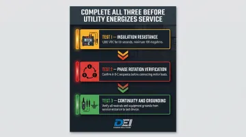
Before the utility energizes the service, three tests are mandatory:
Insulation resistance (megger) testing: Test all feeders and branch circuits at the appropriate voltage. For 600V-class cables, ANSI/NETA ATS prescribes 1,000 VDC applied for one minute, with minimum acceptable resistance of 100 megohms. Low readings indicate damaged insulation, moisture intrusion, or contamination—any of which causes immediate failure on energization.
Phase rotation verification: Use a phase rotation meter to confirm correct phase sequence (A-B-C or 1-2-3) before connecting motor loads. Wrong rotation after startup causes immediate mechanical damage to pumps, fans, conveyors, and compressors. Correcting rotation only requires swapping two phase conductors at the starter, but catching it before first startup avoids the damage entirely.
Continuity and grounding checks: Verify continuity on all neutral and equipment grounding conductors from the service entrance to the last device on every branch circuit. Open grounds and neutrals create shock hazards and equipment damage risks that stay invisible until a fault occurs.
NEC Requirements and Safety Compliance for 480V Service
480V commercial service is governed by multiple NEC articles that apply simultaneously during design, installation, and inspection:
- Article 230 – Service entrance requirements, conductor sizing, and disconnect location
- Article 220 – Load calculations and demand factors
- Article 240 – Overcurrent protection device sizing and selective coordination
- Article 408 – Switchboards and panelboards construction and installation
- Article 110.26 – Working space clearances, which increase at 480V compared to lower-voltage systems
For equipment operating at 151–600V to ground, NEC 110.26(A)(1) sets minimum working space depths based on what is opposite the equipment:
| Condition | What's Opposite | Required Depth |
|---|---|---|
| Condition 1 | Grounded surfaces | 3 feet |
| Condition 2 | Grounded parts on one side, live parts on the other | 3.5 feet |
| Condition 3 | Live parts on both sides | 4 feet |
Minimum width is 30 inches or the equipment width, whichever is greater. Minimum headroom is 6.5 feet. The AHJ verifies all clearances during inspection before issuing approval to energize.
Arc Flash and Electrical Safety Compliance
Three overlapping standards govern arc flash safety and must be applied together:
NEC 110.16 requires arc flash hazard warning labels on all service equipment likely to require examination, adjustment, servicing, or maintenance while energized. Labels must be field-applied before the equipment enters service.
NFPA 70E Section 130.5 mandates an arc flash risk assessment before any energized work. The two compliant methods are the Incident Energy Analysis Method (calculating incident energy in cal/cm² at working distance) and the Arc-Flash PPE Category Method (using tables to select PPE). The key threshold is 1.2 cal/cm²—below this value, standard electrical work clothing may be acceptable; above it, flame-resistant PPE is required.
OSHA 29 CFR 1910.147 governs lockout/tagout (LOTO) procedures for the control of hazardous energy, covering electrical energy sources such as circuit breakers and disconnects.
Required LOTO Sequence for 480V Work
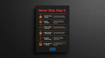
Before any work on 480V equipment, the following LOTO sequence must be followed:
- Identify all energy sources – Locate all circuits, disconnects, and stored energy (capacitors, springs)
- De-energize using normal shutdown procedure – Operate the equipment's normal stop control
- Isolate at the main disconnect – Open the circuit breaker or switch and verify it is mechanically open
- Apply personal lock and tag – Each worker applies their own lock; group lockout procedures apply for crews
- Dissipate stored energy – Discharge capacitors, release spring tension, block mechanical motion
- Verify absence of voltage – Test phase-to-phase and phase-to-ground with a properly rated voltmeter; this is the only confirmation that the circuit is safe to work on
Voltage verification is not optional. Workers have been killed assuming a circuit was de-energized based on breaker position or a co-worker's word. A voltmeter reading zero on all conductors is the only acceptable proof—not breaker position, not a tag, not someone else's assurance.
Common 480V Three-Phase Service Problems and How to Fix Them
Voltage Imbalance Across Phases
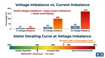
Problem: Phase-to-phase voltages are unequal (e.g., A-B = 482V, B-C = 477V, C-A = 485V), causing motors to overheat and draw excessive current on the most heavily loaded phase. NEMA MG-1 Part 12.45 states motors shall operate successfully at rated load with voltage unbalance not exceeding 1%. Above that threshold, performance degrades rapidly.
A small voltage imbalance produces a disproportionately larger current imbalance — a 2% voltage imbalance can drive a 10% current imbalance in one winding. NEMA MG-1 Part 14.36 derating factors show that at 3% voltage imbalance, the motor must be derated to 88% of nameplate load to prevent overheating and premature insulation failure.
Likely causes:
- Uneven single-phase load distribution across the three phases (lighting, receptacles, small equipment)
- Failing transformer winding with higher impedance on one phase
- Loose connection at the switchboard, panelboard, or MCC bus
Fix:
- Re-balance single-phase loads across all three phases at panelboards and lighting panels
- Tighten all terminations to manufacturer torque specifications
- Measure transformer secondary voltages under load to rule out transformer winding failure
- If imbalance persists after load balancing and connection checks, contact the utility to test the transformer
Single Phasing on a Three-Phase Load
Problem: A three-phase motor hums loudly but won't start, or a running motor suddenly overheats and draws excessive current. One of the three phases has been lost — a condition called single phasing.
When one phase is lost, the remaining two phases must carry the entire load, causing currents to rise sharply (often √3 times or more). Single phasing accounts for approximately 14% of motor failures, and the resulting temperature rise follows the half-life rule: every 10°C above the maximum rating cuts insulation life in half.
Likely causes:
- Blown fuse on one phase
- Open breaker pole (one pole tripped or mechanically failed while the other two remain closed)
- Loose or failed connection at the MCC, panelboard, or motor starter that has interrupted one phase conductor
Fix:
- Open the circuit immediately using the disconnect or circuit breaker to prevent motor burnout
- Test all three phases at the MCC or motor starter terminals with a properly rated voltmeter to identify which phase is lost
- Trace back to the failed component (fuse, breaker, or connection) and repair or replace it
- Verify all three phases are present at the motor terminals before restarting the load
- Monitor motor current on all three phases after restart to confirm balanced operation
Incorrect Phase Rotation After Commissioning
Problem: A newly commissioned motor runs in reverse direction. This is immediately apparent in fans (airflow is backwards), pumps (no flow or low pressure), and compressors (pressure anomalies or mechanical noise). If not caught quickly, reverse rotation can cause mechanical damage to impellers, couplings, and driven equipment.
Likely cause: Two of the three phase conductors were swapped during service entrance conductor termination or at the motor starter, reversing the phase sequence — for example, A-B-C becomes A-C-B. Phase sequence determines rotation direction in three-phase induction motors.
Fix:
- De-energize the circuit and apply LOTO at the motor disconnect
- Swap any two of the three phase conductors at the motor starter or MCC (not at the main switchboard, to avoid affecting other loads)
- Verify correct rotation using a phase rotation meter before reconnecting the motor
- Re-energize and test the motor under no-load conditions first, then under full load
Always confirm phase rotation with a meter before restarting — a 30-second check that prevents a repeat teardown if conductors were re-landed incorrectly.
Frequently Asked Questions
Do commercial buildings have 3-phase power?
Yes, most medium-to-large commercial buildings are served by three-phase power. 480V three-phase is the standard for buildings with significant motor, HVAC, or mechanical loads such as office towers, hospitals, and manufacturing facilities. Smaller commercial spaces (retail, small offices) may be served by 120/208V three-phase, which is sufficient for plug loads, lighting, and small equipment without the heavy motor demands of larger buildings.
Is 480V always 3-phase?
In commercial and industrial practice, 480V is almost universally delivered as a three-phase service. While 480V can technically be derived from a single-phase transformer, single-phase 480V applications are rare and limited to specific equipment scenarios such as resistance heating or specialized process loads. The standard commercial installation is 480Y/277V three-phase, four-wire service.
What is 480 volts used for?
480V three-phase power serves high-demand equipment in commercial buildings: HVAC chillers and rooftop units, elevator motors, large compressors, motor control centers, commercial kitchen equipment (ovens, dishwashers), and as the primary voltage for step-down transformers that supply 120/208V receptacle and lighting panels throughout the building.
What is the acceptable voltage range for 480V systems?
Per ANSI C84.1 voltage tolerance standards, 480V is the nominal distribution voltage and 460V is the utilization voltage at equipment terminals. The acceptable operating range is ±10% of the utilization voltage, or approximately 414V to 506V. Equipment must be designed to operate reliably across this range to account for voltage drop along feeders and load variations on the distribution system.
Is US voltage 460 or 480?
Both terms refer to the same system at different points. 480V is the ANSI/IEEE standard supply voltage from the utility transformer secondary; 460V is the NEMA-designated utilization voltage at the equipment terminals — the difference accounts for line losses along the feeder. When specifying equipment, use the 460V rating; when designing distribution, calculate from the 480V supply.
Need UL 891-certified switchgear for your 480V commercial service project? DEI Power manufactures switchboards from 400A to 4000A using genuine Siemens components, with in-stock availability and engineering support to keep your project on schedule. Contact our specialist team at (866) 773-8050 or email sales@deipower.com for configuration guidance and a same-day quote.