Introduction: Electrical Switchgear Design for Data Centers in 2026
Data center construction is experiencing unprecedented growth. Combined quarterly capital expenditures by Alphabet, Amazon, Meta, and Microsoft exceeded $130B, with 2026 spending projected to surpass $700B driven by AI infrastructure, chips, and power distribution systems. This explosive buildout has transformed electrical switchgear from background infrastructure into a critical design decision—one that determines whether projects succeed or fail.
That pressure lands squarely on engineers, contractors, and facility teams. AI workloads are pushing rack power densities from traditional 10–15 kW to 100–200+ kW per rack, while switchgear lead times have stretched to 50–80 weeks—up from 20–30 weeks just a few years ago.
Code compliance mandates, arc flash labeling requirements, and Buy America Build America procurement rules layer on additional complexity. A single miscalculation in fault current ratings or coordination can jeopardize uptime SLAs worth millions.
TLDR:
- AI-driven rack densities now reach 100–200+ kW, requiring switchgear sized for higher fault currents and distribution capacity
- Switchgear lead times have doubled or tripled; domestic manufacturers offer faster builds and BABA compliance
- UL 891 certification, selective coordination, and arc flash labeling are non-negotiable in mission-critical facilities
- Tier III/IV data centers require redundant switchgear topologies with dual-bus or ring configurations
- Early specification and vendor selection protect schedule and minimize costly field changes
Why Switchgear Design Is More Critical Than Ever in 2026
AI-driven compute workloads have fundamentally changed data center electrical infrastructure. McKinsey reports that AI training racks now demand 100–200+ kW per rack, with some frontier GPU clusters exceeding 1 MW per rack—ten times the traditional 10–15 kW standard. This surge forces engineers to upsize switchgear bus ratings, breaker interrupting capacity, and transformer secondaries to handle fault currents that would have been unthinkable five years ago.
U.S. data center capacity stood at approximately 30 GW in 2025 and is projected to reach 90+ GW by 2030, with hyperscalers capturing roughly 70% of that capacity. Global data centers consumed an estimated 415 TWh in 2024, with projections reaching 945 TWh by 2030. This expansion—across both new builds and retrofits of aging infrastructure—has created historic demand for electrical switchgear at every voltage level.
Key drivers reshaping switchgear requirements:
- Hyperscale and edge facilities require switchgear that scales in phases—without facility shutdowns—using flexible bus architectures and built-in spare capacity
- Rising electricity costs and sustainability regulations push teams toward integrated energy metering, DCIM compatibility, and real-time PUE visibility
- Critical electrical components face 18–36 month lead times, making early specification lock-in and domestic sourcing a project management priority
- Upgrading existing facilities for AI workloads costs 20–30% more per kW than new construction, yet retrofits remain faster in grid-constrained markets where new builds now average 24–36 months
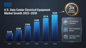
The U.S. data center electrical equipment market is projected to grow from approximately $20B to $65B between 2025–2030, driven by both new capacity and infrastructure upgrades. Switchgear miscalculations carry real consequences: delayed commissioning, arc flash exposure, equipment damage, and cascading outages that can cost operators millions per hour of downtime.
Understanding the Data Center Switchgear Hierarchy: MV vs. LV
As data centers scale past 1 MW of IT load, power distribution can no longer be treated as a single-layer problem. Medium-voltage (MV) and low-voltage (LV) switchgear handle fundamentally different parts of the system — and getting that boundary wrong affects everything from fault coordination to AHJ approval.
Medium-Voltage Switchgear
In large-capacity facilities—typically those exceeding 1 MW IT load—MV switchgear marks the entry point of utility power. Operating above 1,000V (with MV cable ratings commonly spanning 2,001V through 35,000V per NEC Type MV cable classifications), MV switchgear manages incoming utility feeds, backup generator connections, and voltage transformation to the building distribution system.
Key MV switchgear components:
- Incoming feeders from utility grid
- Bus sections for segregating power paths
- Circuit breakers rated for medium-voltage fault currents
- Voltage and current transformers for metering and protection
- Surge arresters and control relays
- Isolation switches for maintenance without de-energizing entire facility
MV switchgear steps power down through MV/LV transformers—typically from 13.8 kV or 34.5 kV utility feeds to 480Y/277V or 208Y/120V distribution voltages serving IT and mechanical loads.
Low-Voltage Switchgear and Switchboards
LV switchgear and switchboards operate below 1,000V and form the backbone of power distribution in most data centers. They receive power from transformer secondaries or generator outputs and distribute it to UPS systems, cooling equipment, power distribution units (PDUs), and IT racks.
Under North American standards, the distinction between switchgear and switchboards matters for compliance:
- Switchboards (governed by UL 891) are dead-front assemblies rated up to 1,000V AC, commonly used for main distribution
- Low-voltage switchgear (governed by UL 1558 and IEEE C37.20.1) provides metal-enclosed compartmentalized construction with draw-out breakers, typically for higher-capacity or higher-reliability applications
This distinction affects submittal documentation, code inspections, and acceptance by authorities having jurisdiction (AHJs).
Automatic Transfer Switches
The ATS bridges utility and generator power during outages, and its transfer characteristics shape the entire system architecture. Open-transition designs introduce a brief interruption; closed-transition (make-before-break) eliminates it — a distinction that directly determines UPS ride-through requirements and battery sizing.
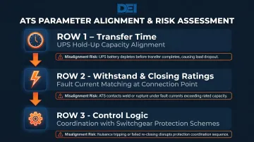
When specifying an ATS alongside switchgear, three parameters must align with your topology:
- Transfer time: Must fall within UPS hold-up capacity to avoid load shedding
- Withstand and closing ratings: Must match available fault current at the point of connection
- Control logic: Must coordinate with switchgear protection schemes to avoid nuisance trips or fault conflicts
Key Switchgear Design Principles for Mission-Critical Data Centers
Short-Circuit Current Rating and Interrupting Capacity
Undersized breakers or bus ratings create catastrophic arc flash and equipment damage risks. Design engineers must calculate available fault current at every distribution level—from utility entry through branch circuits—and specify switchgear with adequate short-circuit current rating (SCCR) and breaker interrupting capacity. Fault current calculations depend on transformer impedance, conductor lengths, and upstream protection devices, requiring coordination studies before equipment selection.
Selective Coordination
Selective coordination ensures that a fault on a branch circuit trips only the nearest upstream device, not the main feed—preserving power to unaffected loads. NEC Articles 700, 701, and 708 mandate it for emergency and critical operations systems. Article 702—which covers many data centers—leaves the decision to engineering judgment, but for mission-critical facilities, selective coordination is non-negotiable regardless of code mandate.
Achieving it requires:
- Time-current curve analysis across all protective devices
- Balancing arc flash incident energy reduction against nuisance trip risk
- Documentation for AHJ review and commissioning sign-off
Load Balancing and Harmonic Distortion
Non-linear server power supplies generate significant harmonic currents—particularly triplen harmonics (3rd, 9th, 15th)—that accumulate in neutral conductors. Improperly sized neutrals and transformers overheat under these conditions, reducing equipment life and risking unplanned shutdowns.
Key mitigation measures include:
- K-factor transformers rated for harmonic loading
- Oversized neutral conductors (typically 200% of phase conductor)
- Periodic power quality monitoring to validate design assumptions against actual loads
Integrated Power Monitoring
Modern switchgear increasingly incorporates metering modules, digital trip units, and remote communications that feed real-time data into DCIM and building management systems. This integration enables PUE tracking, load trending, predictive maintenance, and energy cost allocation by zone—giving operators the data needed to reduce waste, catch load imbalances early, and support sustainability reporting.
UL 891 Certification for North American Projects
UL 891 certification for low-voltage switchboards is a baseline requirement for North American data centers. The standard validates assembly safety, performance, and construction quality—and both contractors and AHJs routinely require it as a condition of project approval.
DEI Power manufactures UL 891-certified switchboards configured to project-specific voltage, layout, and capacity requirements, with full submittal documentation provided for each order.
Redundancy, Tier Standards, and Switchgear Architecture
The Uptime Institute Tier classification system defines data center redundancy and availability expectations, directly shaping switchgear architecture:
Tier Definitions and Switchgear Implications:
- Tier I: Single power path, no redundancy; maintenance requires a full shutdown. Simple main-breaker or main-lug switchgear suffices.
- Tier II: Redundant capacity components but a single distribution path. Switchgear must accommodate spare capacity — dual feeds aren't required.
- Tier III: Concurrently maintainable with redundant distribution paths. Requires dual-bus switchgear with tie breakers so any component can be serviced without IT impact.
- Tier IV: Fault-tolerant with multiple independent, physically isolated systems. Demands fully redundant switchgear lineups with no single point of failure, typically housed in separate fire-rated rooms.
Common Redundant Switchgear Topologies:
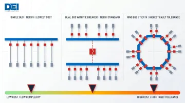
- Single bus: All loads fed from one bus — lowest cost, but maintenance requires an outage. Suitable for Tier I/II.
- Dual bus with tie breaker: Two independent buses with a normally open tie breaker allow load transfer for maintenance. Standard in Tier III facilities.
- Ring bus: Switchgear sections arranged in a ring allow isolation at any point. High fault tolerance comes at increased complexity and cost — common in Tier IV and critical utility applications.
Generator Paralleling Switchgear
Topology selection directly affects how generator systems integrate into the distribution architecture. Higher-tier facilities typically run multiple generators through paralleling switchgear before power reaches the UPS or main distribution bus. Paralleling controls manage voltage matching, frequency synchronization, and load sharing for stable operation during extended utility outages.
Compliance Standards and Certification Requirements for 2026
Data center projects operate under multiple overlapping compliance frameworks — and getting any one of them wrong creates schedule risk, failed inspections, or safety exposure. The primary standards governing switchgear selection and installation include:
Primary Codes and Standards:
- NFPA 70 (National Electrical Code): The 2023 edition is current, with the 2026 edition under development. Governs wiring methods, overcurrent protection, grounding, and system configuration — the baseline for any U.S. electrical installation.
- UL 891: Validates construction, safety, and performance of dead-front switchboard assemblies. Certification confirms the unit meets minimum safety thresholds for low-voltage distribution.
- ANSI/IEEE C37 series: Covers switchgear construction and testing protocols, including IEEE C37.20.1 for metal-enclosed low-voltage power circuit breaker switchgear.
- ANSI/TIA-942: The Telecommunications Infrastructure Standard for Data Centers, defining minimum requirements for cabling, pathways, and electrical distribution in data center environments.
Arc Flash Hazard Analysis and NFPA 70E
NFPA 70E compliance mandates arc flash hazard analysis and labeling on data center switchgear. Engineers must perform short-circuit and coordination studies to determine incident energy levels at each equipment location, then apply labels indicating required PPE categories:
- Category 1: 4 cal/cm²
- Category 2: 8 cal/cm²
- Category 3: 25 cal/cm²
- Category 4: 40 cal/cm²
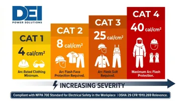
Proper labeling protects maintenance personnel and satisfies OSHA requirements for electrical safety.
Beyond operational safety, public-sector projects carry a separate layer of procurement compliance.
Buy America Build America (BABA) Compliance
Federal and government-funded data center projects require Buy America Build America compliance for domestically manufactured switchgear.
Under BABA, manufactured products must have U.S.-sourced components comprising more than 55% of total component cost. Products must also be permanently affixed to infrastructure to qualify. Switchgear and switchboards fall squarely into this category, making domestic manufacturing documentation a vendor selection criterion for any public-sector project.
Procurement Considerations: Lead Times, Custom Builds, and Supply Chain
Lead times for data center electrical switchgear have become a critical project risk. Standard switchgear from large OEMs now runs 50–80 weeks, with some critical components facing 18–36 month delays. These extended timelines force project teams to specify switchgear early in the design phase, often before final load calculations are complete. That early lock-in creates real vulnerability: design changes downstream can trigger costly reorders and schedule slippage.
One way to reduce that exposure is sourcing from a domestic, in-house manufacturer. Here's what that approach offers in practice:
Advantages of Domestic, In-House Switchgear Manufacturers
- Builds faster by eliminating reliance on outside vendors and overseas factory queues
- Maintains consistent materials, layouts, and testing through vertically integrated manufacturing
- Accommodates last-minute changes to breaker schedules, voltage configurations, or bus layouts without restarting the production cycle
- Simplifies Buy America (BABA) documentation for government-funded projects
DEI Power operates a 50,000 sq. ft. facility in Ontario, CA, producing custom UL 891-certified switchboards with shorter-than-standard lead times and free shipping on all orders — built specifically to keep data center projects on schedule.
What to Provide When Specifying Custom Switchgear
To ensure accurate quoting and avoid costly change orders during construction, project teams should provide:
- Single-line diagrams showing the complete distribution architecture
- Voltage and current ratings for each bus section and feeder
- Breaker schedules with frame sizes, trip settings, and interrupting ratings
- Bus configuration (main-tie-main, dual-bus, etc.)
- AHJ requirements: jurisdiction, inspection standards, and special labeling
- BABA compliance needs, if applicable to the funding source
- Enclosure requirements (NEMA 1 indoor, NEMA 3R outdoor, seismic certification)
Submitting complete specs at the outset keeps quoting fast and revision cycles short — contact DEI Power at sales@deipower.com or (866) 773-8050 to start the process.
Frequently Asked Questions
What is the lead time for data center switchgear equipment?
Lead times vary by manufacturer and project complexity. Standard switchgear from large OEMs can run 50–80 weeks. Domestic manufacturers with in-house fabrication — like DEI Power, which builds UL 891-certified switchboards in Ontario, CA — can deliver on significantly tighter timelines. Specify switchgear early in the design phase to protect your project schedule.
Is electrical switchgear in high demand for data centers?
Yes. Demand for data center switchgear is at a historic high, driven by AI compute buildout, hyperscale construction, and aging infrastructure retrofits. Early procurement planning and vendor selection are critical to avoid delays.
What is the difference between medium-voltage and low-voltage switchgear in a data center?
MV switchgear (above 1 kV, typically 2–35 kV) handles utility entry and large generator connections in higher-capacity facilities. LV switchgear and switchboards (below 1 kV) distribute power to UPS systems, PDUs, and facility loads. LV switchboards in the U.S. are listed under UL 891 — the primary compliance standard for low-voltage distribution equipment in commercial and mission-critical applications.
What certifications should data center switchgear have?
UL 891 is the key listing for low-voltage switchboards in U.S. data centers. Assemblies should also carry NRTL certification per OSHA requirements. Government or public projects may additionally require BABA/Buy America compliance documentation.
What Uptime Institute Tier level is required for data center switchgear redundancy?
The tier requirement depends on the facility's uptime SLA. Tier III and IV data centers require concurrent maintainability and full redundancy (N+1 or 2N), meaning dual power paths and redundant switchgear lineups. Tier I and II allow simpler single-path architectures.