Introduction
Your main switchgear amperage rating is the single most critical specification in commercial and industrial power distribution. It determines whether your facility can safely handle electrical demand, pass code inspections, and accommodate future expansion without costly shutdowns.
Undersized or incorrectly identified switchgear creates serious risks:
- Frequent nuisance tripping under peak loads
- Conductor and bus overheating
- NEC violations that trigger inspection failures
- Unplanned downtime
- Catastrophic failure during fault conditions
NFPA reports approximately 16,930 non-home electrical fires per year involving electrical distribution equipment, causing 22 civilian deaths and $718M in annual property damage.
This guide covers three reliable methods to determine your main switchgear amperage rating: reading the nameplate, calculating facility load per NEC Article 220, and confirming code compliance with safety margins. You'll also find guidance on interpreting results and avoiding the sizing errors that cause the most failures.
Key Takeaways
- Reading the nameplate or main disconnect is the fastest verification method; look for ampere rating (A), voltage (V), and short-circuit current rating (SCCR in kA) stamped on the label or breaker handle
- If the nameplate is missing, calculate total facility load by summing connected equipment amps (I = P/V for single-phase; I = P/(√3 × V) for three-phase), then apply NEC Article 220 demand factors
- NEC codes govern minimum ratings: NEC 230.79 sets service minimums, and the 125% continuous load rule (NEC 215.2 and 230.42) applies to all sizing calculations
- Verify the switchgear SCCR matches or exceeds available fault current at the service point; ampere rating alone does not satisfy code compliance
What You Need to Determine Your Main Switchgear Amperage Rating
Before applying any verification method, gather the right documentation, confirm access permissions, and prepare the proper tools. Attempting to determine switchgear amperage without this preparation leads to incomplete data or unsafe conditions.
Main switchgear refers to the primary service distribution assembly—typically a UL 891-certified switchboard or main distribution panel—that receives utility power and feeds downstream branch circuits or sub-panels. Sub-panels, by contrast, are secondary distribution panels fed from the main switchgear.
Tools and Documentation Required
- Equipment nameplate or facility single-line diagram showing the service entrance and main distribution equipment
- Clamp meter (1000A minimum range) for live load measurement if needed
- Current electrical drawings or as-built plans showing service size, transformer capacity, and major loads
- NEC reference (2023 or current edition adopted by your jurisdiction)
- PPE: Arc flash-rated gloves, safety glasses, insulated voltage-rated tools, and long-sleeve FR clothing per NFPA 70E Table 130.7(C)(15)
Preconditions and Setup
Before opening any switchgear enclosure:
- Verify an arc flash assessment has been completed for the equipment location and that the incident energy or PPE category is known
- Confirm work conditions: De-energized inspection is preferred; if work must be performed live, follow NFPA 70E lockout/tagout (LOTO) procedures and use appropriate arc-rated PPE
- Ensure only qualified persons per NFPA 70E definitions perform the inspection—individuals trained on electrical hazards, proper PPE selection, and shock/arc flash boundaries
With the right tools staged and safety conditions confirmed, you're ready to apply the verification methods covered in the next section.
Method 1: Read the Switchgear Nameplate and Main Disconnect
Every UL 891-listed switchboard must carry a permanently affixed, visible nameplate specifying its ampere rating, voltage class, and short-circuit rating. This is the most direct method—it confirms the rated capacity as designed and built by the manufacturer, not necessarily the current operating load.
Here's how to read it correctly.
Step-by-Step
Step 1: Locate the switchgear enclosure. In commercial and industrial facilities, main switchgear or switchboards are typically installed in dedicated electrical rooms, mechanical rooms, or at the utility service entrance. Ensure the area is clean, well-lit, and accessible.
Step 2: With proper PPE, open the enclosure door and locate the main disconnect device. This could be a main circuit breaker, fusible switch, non-fused disconnect, or bolted pressure switch. The ampere rating is stamped directly on the handle, faceplate, or an adjacent rating label (e.g., 800A, 1200A, 2000A).
Step 3: Find the equipment nameplate, usually affixed inside the door or on the back panel. Record:
- Ampere rating (A)
- Voltage (V)
- Number of phases and frequency (Hz)
- Short-circuit current rating (SCCR or withstand rating in kA or amperes RMS symmetrical)
- UL listing marks (e.g., "UL 891 Listed Switchboard")
Step 4: Cross-reference the main disconnect ampere rating with the nameplate bus ampere rating. If they differ, the effective rating is the lower of the two values. A 2000A bus with a 1600A main breaker limits the service to 1600A.
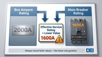
That comparison alone can prevent costly mistakes during load planning or equipment upgrades.
When This Method Works — and When It Doesn't
Advantages:
- Takes under five minutes with no calculations required
- Provides the manufacturer's rated capacity directly
- Works on any UL 891-listed switchboard
Limitations:
- Nameplates may be worn, painted over, or missing after renovations
- Field modifications — such as breaker upgrades or bus extensions — may have changed the configuration without updating the label
- The nameplate rating won't tell you whether current or planned loads still fall within that capacity
Method 2: Calculate Your Facility's Total Electrical Load
When the nameplate is missing, illegible, or you need to verify that existing switchgear is properly sized for actual demand, a load calculation per NEC Article 220 is the correct approach. This method produces the minimum required ampacity your switchgear must be rated to handle.
Step 1 — Inventory All Connected Loads
List every electrical load in the facility:
- Lighting (interior, exterior, emergency)
- HVAC equipment (rooftop units, chillers, air handlers)
- Motors (pumps, fans, compressors)
- Receptacles (general-use, dedicated equipment)
- Process equipment, EV chargers, UPS/server loads
Record each load's wattage (W) or kilowatt (kW) rating from equipment nameplates.
Then organize loads into two categories: continuous (operating 3+ hours at a time) and non-continuous. This distinction is critical for applying the 125% safety factor in the next steps.
Step 2 — Convert Loads to Amperes
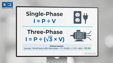
Use the appropriate formula based on system type:
Single-phase: I (amps) = P (watts) / V (volts)
Three-phase: I (amps) = P (watts) / (√3 × V)
Example: A 100 kW three-phase load at 480V:
I = 100,000 W / (1.732 × 480 V) ≈ 120.3 A
Apply this formula to each load category to produce an ampere total.
Step 3 — Apply NEC Demand Factors
Not all loads operate simultaneously at full capacity. NEC Article 220 permits demand factors for:
- Lighting loads (NEC 220.42)
- Receptacle loads (NEC Table 220.44)
- Electric heating (NEC 220.51)
- Air conditioning and refrigeration equipment (NEC 220.50)
Applying these factors reduces the calculated load to a realistic operating demand, ensuring the switchgear is sized for actual service conditions rather than theoretical maximums.
Step 4 — Total the Load and Determine Minimum Ampacity
Sum all adjusted loads (after demand factors) to arrive at total demand in amps. The main switchgear must be rated at or above this figure. NEC 230.79 specifies minimum service ampacity based on facility type:
- Commercial/industrial: minimum 60A, though most require 400A–4000A depending on scale
- One-family dwelling: minimum 100A
Pros and Cons
Pros:
- Verifies whether existing or planned switchgear is correctly sized
- Enables proactive planning for future load additions
- Meets engineering documentation requirements for inspections and insurance
Cons:
- Requires access to accurate equipment data
- Incomplete load inventory makes results unreliable
- Correct application of demand factors varies by load type and requires expertise
Method 3: Apply NEC Safety Margins and Confirm Code Compliance
A load calculation gives you a starting number — NEC gives you the floor. Mandatory safety margins and minimum specifications must be applied on top of calculated demand. Miss this step and switchgear that clears initial inspection can still fail under sustained loads or fault conditions.
The 125% Rule for Continuous Loads
NEC 215.2(A)(1) and 230.42 require that switchgear ampere rating and overcurrent protection must be at least 125% of continuous load current plus 100% of non-continuous load current.
Example:
- Continuous load = 400A
- Non-continuous load = 100A
- Minimum switchgear rating = (400A × 1.25) + 100A = 600A
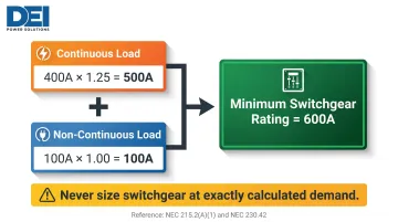
Never select switchgear rated at exactly the calculated demand. The 125% margin prevents thermal fatigue, nuisance tripping, and premature component failure from loads operating at full current for extended periods.
Ampere rating addresses continuous capacity — but it tells you nothing about fault tolerance. That's where SCCR comes in.
Verify the Short-Circuit Current Rating (SCCR)
Ampere rating and interrupting rating are two separate specifications — both must be correct. The switchgear's SCCR (in kA) must equal or exceed the available fault current at the point of service, which is determined by:
- Utility transformer size and impedance
- Service entrance conductor length and size
- On-site generation or energy storage systems
- Formal short-circuit study performed by a licensed engineer
Undersized SCCR can result in catastrophic switchgear failure during a fault event, even if the ampere rating is correct. NEC 110.10 requires equipment to have adequate SCCR for the circuit's available fault current.
Check for Future Load Growth
Most electrical engineers recommend sizing switchgear with 20–25% spare capacity beyond current calculated demand to accommodate future equipment additions:
- EV charging infrastructure
- HVAC upgrades or expansions
- New production machinery
- IT or data center loads
Adding new loads to a system running at 95% of rated capacity is a common cause of undersized switchgear scenarios in existing facilities. U.S. electricity demand is projected to grow 3% in 2027, the strongest four-year growth since 2007, driven largely by data centers and industrial electrification.
Confirm Local AHJ Requirements
Beyond NEC minimums, the Authority Having Jurisdiction (AHJ)—your local building department or electrical inspector—may impose stricter requirements for certain occupancy types:
- Hospitals and healthcare facilities
- Data centers and telecom installations
- Industrial facilities with hazardous locations
NEC 90.4 grants the AHJ authority to interpret code provisions and approve equivalencies. Always verify local amendments before finalizing switchgear selection.
How to Interpret Your Results
Once you've confirmed the nameplate amperage and completed a load calculation, your findings will fall into one of three categories—each requiring a different response.
Adequate Rating (No Action Required)
The nameplate ampere rating equals or exceeds 125% of continuous load plus 100% of non-continuous load, and the SCCR meets or exceeds available fault current. The switchgear is correctly sized.
Recommended action: Document the finding in your facility electrical maintenance records and schedule the next load review when significant equipment is added or after 5 years, whichever comes first per NFPA 70B maintenance intervals.
Undersized or Approaching Capacity (Action Recommended)
The switchgear is operating at more than 80% of rated ampacity, or will exceed code-compliant minimums with planned load additions. An upgrade or replacement should be planned.
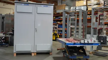
When specifying a replacement, DEI Power manufactures custom UL 891-certified switchboards from 400A through 4000A, built to exact voltage and layout requirements. Units use genuine Siemens components, are BABA-compliant, and ship from their Ontario, California facility with 4–6 week lead times for built-to-order configurations.
Out-of-Spec or Unverifiable Rating (Immediate Action Required)
The nameplate is missing, the SCCR is below available fault current, or field conditions suggest undocumented modifications. Do not assume the installed rating is safe.
Commission a licensed electrical engineer to perform a full short-circuit and load study before adding any new loads. Operating with unverified switchgear exposes personnel to shock and arc flash hazards and creates significant liability exposure.
Common Errors and Safety Precautions
Two calculation mistakes account for most sizing errors in the field:
- Main breaker vs. bus rating mismatch: The main overcurrent protective device (breaker or fuse) may be rated below the switchgear bus rating. The effective limit of the assembly is always the lower of the two values — never assume the bus rating defines the service limit if the main breaker is rated lower.
- Skipping the 125% continuous load factor: A common mistake is calculating total load and assuming the switchgear just needs to match or slightly exceed it. Skipping the 125% multiplier on continuous loads produces switchgear that is technically undersized under NEC, even when it looks correct on paper.
Physical inspection carries its own risks. Follow these precautions before touching any equipment:
- Never open energized switchgear without proper arc flash PPE per NFPA 70E
- Apply lockout/tagout (LOTO) procedures before any physical inspection of internal components
- Never rely on visual inspection alone — always compare nameplate data against actual system load data and available fault current
Conclusion
Determining your main switchgear amperage rating requires three aligned steps: reading the nameplate and main disconnect, calculating total facility demand load with NEC Article 220 demand factors, and confirming that the resulting rating satisfies NEC continuous load safety margins and SCCR requirements. An ampere rating that appears correct on a label is only valid when verified against actual load and fault current conditions.
Unverified switchgear amperage puts personnel, equipment, and operations at risk. When sizing new switchgear or replacing an undersized assembly, working with a manufacturer that provides code-compliant, custom-built solutions means correct amperage, voltage, and SCCR requirements are confirmed before equipment ships — not discovered during installation.
DEI Power provides engineering support throughout the selection process for commercial, industrial, and utility applications. Contact our team at (866) 773-8050 or sales@deipower.com for configuration guidance and project support.
Frequently Asked Questions
What is the 125% rule in electrical?
Under NEC 215.2 and 230.42, the overcurrent protective device and conductor feeding a continuous load must be rated at no less than 125% of that continuous load current. This prevents thermal fatigue and nuisance tripping from loads operating at full current for 3 or more hours.
Which standard ampere ratings are commonly used for main switchgear?
Common standard ratings for commercial and industrial switchgear include 400A, 600A, 800A, 1000A, 1200A, 1600A, 2000A, 2500A, 3000A, and 4000A per NEC 240.6. Unlike residential panels, main switchgear follows higher-tier standard increments governed by manufacturer frame sizes and NEC requirements.
When should you use a higher interrupting rating (e.g., 65kA vs. 100kA) on switchgear?
The switchgear's interrupting or SCCR rating must match or exceed the available fault current at the service point, determined by a short-circuit study. Facilities closer to the utility transformer or with on-site generation typically see higher available fault currents and require higher-rated equipment per NEC 110.10.
What happens if your main switchgear is undersized?
Consequences include:
- Frequent tripping under peak loads
- Overheating, fire risk, and NEC code violations
- Potential insurance liability
- Catastrophic failure if a fault exceeds the switchgear's SCCR
Undersized switchgear that hasn't failed yet is not safe. It is one wrong load condition away from failure.
How often should you re-evaluate your switchgear amperage rating?
Re-evaluate after any significant load addition (HVAC upgrades, EV charging, new machinery), after facility expansions, and during routine electrical audits every 5–10 years per NFPA 70B or AHJ requirements. A load profile that was accurate at installation can run 20–30% higher within just a few years.