Errors at the service entrance level—such as wrong wire sizing, poor bonding, or missed code requirements—create serious downstream consequences. These mistakes lead to failed inspections, equipment damage, and safety hazards that are expensive and time-consuming to correct after energization.
This guide covers the complete installation process for a 400A 3-phase service entrance, from site prerequisites and NEC-compliant wire sizing to step-by-step installation, validation, and common problem-solving.
Key Takeaways
- A 400A 3-phase service entrance requires licensed installation, AHJ permits, and utility coordination before work begins
- Wire sizing follows NEC Table 310.16 using parallel 250–350 kcmil aluminum conductors per phase, derated for temperature and conduit fill
- Sequence matters: site prep and conduit must be complete before pulling conductors, bonding, or calling for utility energization
- Validation before energization includes insulation resistance testing, torque verification, phase rotation check, and voltage confirmation
- Skipping grounding, bonding, or load calculations causes failed inspections and creates direct life-safety hazards
400 Amp 3-Phase Service Entrance: Installation Guide
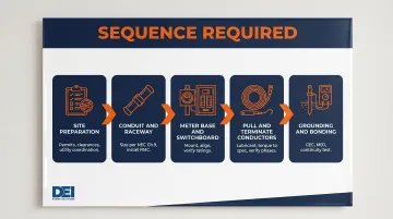
The installation process consists of four stages: preparation and coordination, physical infrastructure (conduit, meter base, switchboard), conductor installation and termination, and grounding/bonding. Each stage must be completed in sequence before the next begins.
A commercial 400A 3-phase service entrance requires coordination across utility providers, AHJ inspectors, contractors, and equipment suppliers across multiple site visits. Skipping steps or rushing the sequence creates rework, failed inspections, and code violations. Start with the prerequisites below before touching anything on site.
Prerequisites and Safety Considerations
Three non-negotiable prerequisites must be completed before installation begins:
- Completed load calculation per NEC Article 220 to confirm 400A 3-phase service is required
- Permit issued by the Authority Having Jurisdiction (AHJ)
- Written service agreement or approval from the local utility company specifying metering and equipment requirements
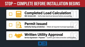
According to Avista's Commercial Electric Service Requirements, utility approval is required before work begins, and a passed inspection by the AHJ does not constitute Avista approval. A signed service agreement and payment are required before the utility schedules connection work.
Site readiness requirements per NEC 110.26:
- Working clearance depth (Table 110.26(A)(1)):
- 0-150V to ground: 3 feet (Condition 1 and 2)
- 151-600V to ground: 3 feet (Condition 1) or 3.5 feet (Condition 2)
- Width: Minimum 30 inches or equipment width, whichever is greater
- Height: Minimum 6 feet 6 inches or equipment height
- Dedicated space free from piping and non-electrical equipment
- Structural considerations for equipment weight and mounting
Compatibility checks before ordering equipment:
- Voltage configuration (208V or 480V Wye vs. 240V/480V Delta)
- Fault current rating (AIC) of the service entrance switchboard—must equal or exceed available fault current at the service point
- Meter base rating and compatibility with utility requirements
- Main disconnect type
Equipment mismatches found after installation mean costly change orders. DEI Power's UL 891-certified switchboards are custom-configured for the exact service voltage, layout, and AIC rating required—before the unit ships.
Do not proceed if:
- Utility approval has not been received
- Permit has not been issued
- Fault current level at the service point is unknown
- Site clearances are non-compliant
Proceeding without these exposes the contractor to liability and the facility to unsafe operating conditions. Once those conditions are confirmed, verify PPE and safety protocols before any physical work begins.
PPE and safety requirements:
- Arc flash PPE rated to the available fault current—NFPA 70E 2024 specifies PPE categories ranging from 4 cal/cm² (Category 1) to 40 cal/cm² (Category 4)
- Lockout/tagout procedures during installation before utility energization
- A second qualified person present during energization (becoming mandatory in NFPA 70E-2027)
Wire Sizing and Component Selection for 400 Amp 3-Phase Service
With site conditions confirmed and safety requirements addressed, the next step is specifying conductors and equipment. Wire sizing for 400A 3-phase service is not a simple lookup—unlike residential single-phase service, the commercial 83% dwelling allowance does not apply. Each phase conductor must carry the full calculated load.
NEC Table 310.16 ampacity values at 75°C:
Copper:
- 250 kcmil: 255A
- 350 kcmil: 310A
- 500 kcmil: 380A
Aluminum/Copper-Clad Aluminum:
- 250 kcmil: 205A
- 350 kcmil: 250A
- 500 kcmil: 310A
Source: NEC Table 310.16 (2020 edition)
Parallel conductors as the standard approach:
Running two parallel sets per phase is preferred over single very large conductors due to:
- Easier handling and installation
- Greater flexibility in conduit routing
- Reduced pulling force requirements
NEC paralleling rules (310.10(H)):
All conductors in a parallel set must be:
- Identical material (copper or aluminum)
- Same insulation type
- Same length
- Same circular-mil area
- Terminated in the same manner
- Same number of conductors where in separate raceways
Example parallel conductor sizing:
Two parallel sets of 250 kcmil aluminum per phase at 75°C = 205A each × 2 = 410A total capacity.
Adjustment and correction factors:
Before finalizing wire size, apply these factors to Table 310.16 ampacity values:
Ambient temperature correction (above 30°C requires derating):
- 31-35°C: multiply by 0.94
- 36-40°C: multiply by 0.88
- 41-45°C: multiply by 0.82
Conduit fill adjustment (more than three current-carrying conductors):
- 4-6 conductors: multiply by 0.80
- 7-9 conductors: multiply by 0.70
- 10-20 conductors: multiply by 0.50
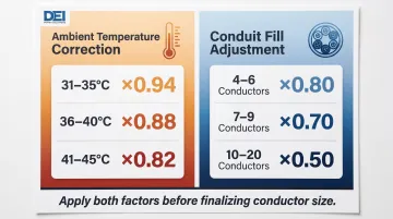
These factors can require stepping up conductor size beyond the baseline table value.
Grounding and bonding conductor sizing:
Grounding Electrode Conductor (GEC) is sized from NEC Table 250.66:
- Service conductors over 350 kcmil through 600 kcmil Cu → 1/0 AWG Cu GEC
- Service conductors over 250 kcmil through 500 kcmil Al → 1/0 AWG Cu or 3/0 AWG Al GEC
- Exception per 250.66(A): For rod, pipe, or plate electrodes, GEC not required to be larger than 6 AWG Cu
Main Bonding Jumper (MBJ) and Equipment Bonding Jumper (EBJ) are sized from NEC Table 250.102(C)(1):
- Service conductors over 350 kcmil through 600 kcmil Cu → 1/0 AWG Cu bonding jumper
- Service conductors over 1100 kcmil Cu equivalent (paralleled) → 12.5% of combined area
Service entrance switchboard selection criteria:
The switchboard must:
- Carry an AIC rating equal to or greater than the available fault current at the service point (per NEC 110.9)
- Be rated for the system voltage and configuration (3-phase 3-wire or 3-phase 4-wire)
- Meet UL 891 listing requirements for low-voltage switchboards
Confirming these specs before ordering eliminates the specification mismatches that generate field change orders.
How to Install a 400 Amp 3-Phase Service Entrance: Step-by-Step
Installation follows a strict sequence. Out-of-order work—such as pulling conductors before conduit is inspected or energizing before grounding is complete—creates rework, failed inspections, and safety hazards.
Step 1 — Site preparation and coordination
- Confirm utility service point location and service drop method (overhead vs. underground)
- Obtain all permits from the AHJ
- Mark and verify clearances per NEC 110.26
- Coordinate the utility's scheduled energization date before any physical work begins
The utility typically requires inspection sign-off before they will connect. Per Avista's requirements, Avista has final approval regardless of AHJ inspection results.
Step 2 — Install conduit and raceway system
- Size conduit per NEC Chapter 9 fill tables based on conductor quantity and size
- Specify conduit type appropriate to the installation environment—rigid metal conduit (RMC) is standard for service entrance raceways exposed to physical damage per NEC 230.43
- Install conduit supports per NEC spacing requirements
- Ensure the raceway route avoids heat sources and provides adequate pulling access
Step 3 — Set the meter base and service entrance switchboard
- Mount the utility-approved meter base at the required height and location
- Install the service entrance switchboard (main distribution section) directly downstream
- Ensure the equipment is level, properly secured, and incoming conductor entry points align with conduit routing
- Verify equipment ratings match the approved plans before securing permanently
Step 4 — Pull and terminate service conductors
- Pull conductors carefully using appropriate pulling lubricant and a pulling tension monitor to avoid damaging insulation
- Terminate conductors to the correct lugs using the lug manufacturer's torque specifications (manufacturer-specific torque values vary; consult equipment documentation)
- Verify each phase is landed on the correct terminal and that parallel conductor sets are equal in length
- Undertorqued lugs are one of the leading causes of service entrance failures—torque verification is mandatory per NETA ATS acceptance testing standards
Step 5 — Install and verify the grounding and bonding system
- Install ground rods or other grounding electrodes per NEC Article 250 (minimum 8 feet in contact with soil; multiple electrodes must be at least 6 feet apart per NEC 250.53)
- Connect the GEC from the service switchboard to the grounding electrode system
- Install the Main Bonding Jumper connecting the neutral bar to the equipment grounding terminal per NEC 250.28
- Verify all connections are torqued per manufacturer specs
- Test ground continuity before calling for utility connection
Post-Installation Checks and Validation
Insulation Resistance Test (Megger Test)
Before energization, perform a Megger test on each service conductor to verify insulation integrity. For 600V-rated service conductors:
- Test voltage: 1,000 VDC
- Test duration: 1 minute
- Minimum acceptable reading: 100 megohms
Lower readings indicate a compromised conductor or connection that must be investigated before energization. NETA ATS acceptance testing standards specify these parameters.
Electrical Verification Sequence at Energization
After the utility connects:
- Verify correct phase rotation using a phase rotation meter—reversed phase rotation damages motors and three-phase loads
- Measure line-to-line and line-to-neutral voltages at the switchboard to confirm they match the design voltage within acceptable tolerance (ANSI C84.1 Range A specifies ±5% of nominal)
- Check for balanced loading across all three phases
Skipping any of these steps transfers risk forward — where the cost of fixing it rises sharply:
- A torque issue discovered after energization requires a planned outage for repair
- Incorrect phase rotation may not be caught until connected equipment fails
- Incomplete grounding discovered during a fault event creates a life-safety emergency
Document all test results before signing off. A completed validation record gives the facility a baseline for future troubleshooting and protects the installer if issues surface later.
Common Installation Problems and How to Fix Them
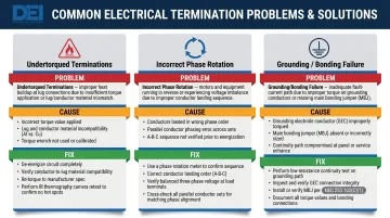
Undertorqued or Incorrect Conductor Terminations
Hot connections, intermittent breaker trips, or visible discoloration at lugs almost always point to one of two root causes: lug terminations not torqued to manufacturer spec, or a conductor landed on the wrong-rated lug (copper conductor in an aluminum-only lug, or vice versa).
To fix it:
- De-energize the system
- Verify conductor-to-lug material compatibility — NEC 110.14(A) requires terminals to be identified for the conductor material
- Re-terminate with a calibrated torque wrench to manufacturer spec
- Re-test with an IR camera after re-energization
Incorrect Phase Rotation or Phase-to-Phase Imbalance
When 3-phase equipment — motors, VFDs, HVAC compressors — runs backwards, trips on fault, or draws unbalanced current, the culprit is usually phases landed in the wrong order during termination, a utility connection error, or a conductor mistake during parallel set installation.
To fix it:
- De-energize the system
- Use a phase rotation meter to confirm sequence before reconnecting any loads
- Correct termination order as needed
- Verify balanced voltage across all three phases before re-energization
Inadequate Grounding or Bonding Continuity
Nuisance tripping, energized equipment enclosures, or ground fault protection activating without a clear load-side fault are classic signs of a grounding or bonding failure. The most common causes are an improperly torqued GEC or MBJ connection, incorrect GEC sizing, or a missing neutral-to-ground bond at the service point.
To fix it:
- Perform a ground continuity test
- Inspect all GEC and bonding connections
- Verify the MBJ is present and properly sized per NEC Table 250.102(C)(1)
- Re-torque all grounding connections
Pro Tips for Installing a 400 Amp 3-Phase Service Entrance Effectively
Specify All Equipment Before Pulling Permits
The meter base type, switchboard AIC rating, conduit entry configuration, and main disconnect type must all be finalized and approved on permit drawings before installation begins. Late equipment changes are the most common source of rework and schedule delays on commercial service entrance projects.
Suppliers like DEI Power build custom switchboards to a project's exact voltage, layout, and fault current specs — which cuts down on last-minute configuration changes that derail timelines.
Document Every Torque Value, Test Result, and As-Built Measurement
Create a sign-off sheet for:
- Conductor termination torque
- Megger test results
- Phase rotation confirmation
- Voltage readings
This documentation protects the contractor during inspections, satisfies AHJ requirements, and provides the facility team with a baseline for future maintenance.
Know When to Pause and Re-Engage the Utility or AHJ
Some field conditions require stopping work entirely. Pause and resolve before moving forward if:
- Available fault current at the service point is higher than the switchboard's AIC rating
- Utility specifies different metering equipment than planned
- Field conditions make planned conduit routing unsafe
Resolving these issues mid-project costs far less time than addressing code violations after the inspection fails.
Conclusion
A 400A 3-phase service entrance sets the foundation for every electrical system downstream. Errors in wire sizing, grounding, bonding, or equipment selection compound throughout the facility and are expensive to correct after energization.
Three phases separate a compliant installation from a costly callback:
- Load calculations, permits, and utility coordination — done before a single conduit is pulled
- Torque specs, correct sequencing, and grounding verification — executed without shortcuts during installation
- Post-installation validation — completed and documented before handoff, not after problems surface
Get all three right, and the service entrance performs reliably for decades. Skip any one of them, and the rework will cost far more than doing it correctly the first time.
Frequently Asked Questions
What are the requirements for a 400 amp service entrance?
A 400A service entrance requires an AHJ permit, completed NEC Article 220 load calculation, utility approval, properly rated and UL-listed service entrance equipment (meter base, switchboard, main disconnect), NEC 110.26 clearances, and NEC Article 250-compliant grounding and bonding.
What size wire do I need for a 400 amp 3 phase service?
Each phase conductor must be sized to carry 400A continuously per NEC Table 310.16 using the 75°C column. Parallel conductor sets are the common approach—typically two parallel sets of 250-350 kcmil aluminum or equivalent copper per phase, subject to ambient temperature and conduit fill derating. Always verify final sizing against your adopted NEC edition and AHJ requirements.
What size wire for 400 amp 3 phase service parallel?
With two parallel sets per phase, each set must independently carry half the required ampacity. A common configuration is 250 kcmil aluminum XHHW-2 per set (205A each at 75°C per NEC Table 310.16, totaling 410A per phase) — apply all applicable derating factors before finalizing.
What size bonding wire do I need for a 400 amp service?
The Main Bonding Jumper and Equipment Bonding Jumper are sized from NEC Table 250.102(C)(1) based on the service conductor size. For service conductors over 350 kcmil through 600 kcmil copper, the bonding jumper is 1/0 AWG copper. The Grounding Electrode Conductor is sized from NEC Table 250.66 based on the largest ungrounded service conductor or equivalent parallel area.
Is 400 amp service 3 phase?
400A service can be either single-phase (common in large residential installations using two 200A panels) or 3-phase (standard in commercial and industrial applications). 3-phase 400A service is the configuration covered in this guide and is distinct from residential split-phase service in voltage options, conductor requirements, and equipment specifications.