Introduction
Most failed inspections on 400A dual-disconnect installations trace back to the same handful of errors: improper conductor sizing, missing grounding electrodes, and metering configurations the utility won't accept. This setup is more complex than a single 400A disconnect — it introduces metering coordination, grounding electrode system design, and bonding requirements across two service entrance points that all have to align.
NEC 230.71(B) explicitly permits two to six service disconnects, but permission isn't the same as compliance. Every requirement for grouping, labeling, conductor sizing, and grounding still applies in full.
This work requires licensed electricians or electrical contractors with commercial or industrial service installation experience. Improper conductor sizing, missing grounding electrodes, or utility metering non-compliance leads to costly rework, failed inspections, and unsafe operating conditions — none of which are recoverable without pulling the work apart.
This guide walks through the complete installation sequence: pre-work coordination, NEC code requirements, conductor sizing, grounding electrode design, and post-installation validation — everything needed to submit a 400A dual-disconnect installation that passes inspection on the first review.
Key Takeaways
- A 400A service with two 200A disconnects is permitted under NEC 230.71(B), which allows up to six service disconnects instead of a single main
- Wire sizing (NEC Table 310.15(B)(16)), metering configuration, and a compliant grounding electrode system must all be correct before energizing
- Installation follows a defined sequence: utility coordination → service entrance → disconnect enclosure → conductor termination → grounding → validation
- Skipping utility approval or permit pull before work begins is a common and costly mistake
- Pre-engineered, UL 891-listed switchboards cut code compliance risk and reduce field rework
What Is a 400 Amp Service with Two 200 Amp Disconnects — and Why Is This Configuration Used?
Instead of a single 400A main breaker, NEC 230.71(B) permits the service disconnect to consist of up to six individual disconnects. Two 200A disconnects satisfy this rule and collectively deliver 400A service capacity.
Both disconnects must be positioned at the service entrance point — not downstream in sub-panels — and grouped together, clearly labeled, and accessible per NEC 230.70 and 230.72.
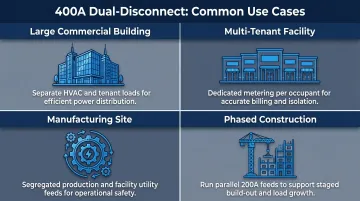
Common Use Cases
This configuration is frequently used in:
- Large commercial buildings that need separate distribution systems for HVAC and tenant loads
- Multi-tenant facilities where each occupant requires dedicated metering and disconnect control
- Manufacturing sites running segregated feeds for production equipment and facility systems
- Phased construction projects where parallel 200A feeds are more practical than a single 400A switchboard
Trade-offs to Consider
Dual-disconnect configurations offer load separation and installation flexibility, but they demand more coordination than a single-disconnect setup. Most installation errors surface in three areas:
- Utility metering requirements and service entrance compliance
- Neutral-to-ground bonding location
- Grounding electrode conductor sizing
Getting these right is what separates a clean inspection from a costly callback.
Before You Begin: Prerequisites, Safety, and Required Materials
Pre-Installation Requirements
Before any physical work begins, confirm:
- Submit your service upgrade request and confirm metering requirements (self-contained vs. CT metering)
- Obtain a valid permit from the Authority Having Jurisdiction (AHJ) before proceeding
- Confirm available fault current (SCCR) to ensure disconnect ratings are adequate for the site's short-circuit level
- Verify the meter socket or CT cabinet supports 400A service per utility specs
With approvals in place, the next priority is safety. All personnel must follow these requirements before any termination work begins.
Safety Non-Negotiables
- De-energize upstream before any termination work — Lockout/Tagout (LOTO) is mandatory
- Wear PPE rated for the service entrance arc flash hazard level
- Proceeding without utility approval or permits risks failed inspections, forced rework, and legal liability
Once safety requirements are confirmed, gather all materials before mobilizing to the site.
Materials Checklist
Equipment & components:
- Two 200A disconnect enclosures listed for use as service entrance equipment
- Service entrance conductors per NEC Table 310.15(B)(16) — minimum 250 kcmil aluminum or 3/0 AWG copper per conductor set
- Meter socket or CT cabinet rated for 400A service
- Grounding electrode conductors and electrodes (ground rods per NEC 250.52)
- Conduit sized per local code — typically 3-inch rigid metal conduit for service entrance
Tools required:
- Torque wrench, conduit bending equipment, and wire pulling tools
- Insulation resistance tester
Step-by-Step Installation Guide for 400 Amp Service with Two 200 Amp Disconnects
Installation follows a strict sequence, and each phase must be confirmed complete before advancing. Shortcuts in termination or grounding are the leading cause of inspection failures and unsafe installations.
Coordinate with the Utility and Pull Permits
Contact the serving utility to request a 400A service upgrade and confirm metering requirements. Most utilities require CT metering for services above 200A, but requirements vary by region. Submit permit applications to the AHJ and obtain approval before ordering materials or breaking ground.
Critical: Utilities often have specific requirements for meter socket ratings, seal-off fittings, and service entrance conduit entry points. Get these in writing before purchasing equipment.
Install the Service Entrance Conduit and Metering Infrastructure
Install the weatherhead or underground service entry conduit, pulling to the meter socket or CT cabinet location per utility specs. Mount the meter socket or CT cabinet—for 400A service, a CT cabinet is typically required.
Conduit sizing: Per NEC Table C8, 3-inch rigid metal conduit accommodates seven 250 kcmil THHN conductors at 40% fill—sufficient for a single 200A feed. Plan for two parallel 3-inch RMC runs, one per 200A disconnect.
Mount and Secure the Two 200A Disconnect Enclosures
Mount both 200A disconnect enclosures adjacent to (or directly below) the metering equipment, in compliance with NEC 230.70 requirements for service disconnect placement. Disconnects must be:
- Accessible and permanently marked "SERVICE DISCONNECT" per NEC 230.70(B)
- Grouped together per NEC 230.72
- Listed for service entrance use and rated for the available fault current at the service point
If using a pre-engineered switchboard with integrated dual 200A disconnects, confirm it carries a UL 891 listing. Sourcing equipment from a manufacturer like DEI Power, which builds UL 891-certified switchboards with in-house engineering support, removes guesswork around field configuration and reduces the chance of inspection delays.
Pull and Terminate Service Entrance Conductors
Pull two separate sets of service entrance conductors—one set per 200A disconnect—from the meter socket/CT cabinet to each disconnect enclosure.
Minimum conductor sizes per NEC Table 310.15(B)(16):
- Copper: 3/0 AWG minimum (200A at 75°C terminals)
- Aluminum: 250 kcmil minimum (205A at 75°C terminals)
Maintain conductor bundling, bend radius, and fill requirements throughout. Terminate at the line lugs of each disconnect using manufacturer-specified torque values. Per NEC 110.14(D), torque must be applied per manufacturer specs using an approved torque tool. While the 2023 NEC removed the documentation requirement, record all torque readings—many AHJs and project specifications still require it.
Install the Grounding Electrode System
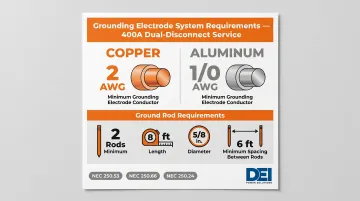
Install the grounding electrode system per NEC Article 250:
Ground rod requirements:
- Minimum two ground rods per NEC 250.53(A)(2), unless a single rod tests below 25 ohms resistance to earth
- Minimum 8 feet in length, 5/8-inch diameter (copper-clad steel)
- Spaced at least 6 feet apart per NEC 250.53(A)(3)
Grounding electrode conductor sizing:
For a 400A service with dual 200A feeds using 250 kcmil aluminum per feed, NEC Table 250.66 requires:
- 2 AWG copper minimum, or
- 1/0 AWG aluminum minimum
Neutral-to-ground bonding:
Per NEC 250.24(B), the neutral-to-ground bond must be made at the service entrance—not at downstream panels. Each 200A service disconnect enclosure must have its own main bonding jumper connecting the equipment grounding conductors and the service-disconnect enclosure to the grounded conductor (neutral).
Post-Installation Checks and Validation
With wiring complete and panels closed, validation confirms the installation is safe, code-compliant, and ready for utility energization. Work through these checks in sequence — skipping steps here is where most last-minute inspection failures originate.
Visual and Mechanical Inspection
Before requesting utility energization, conduct a thorough inspection:
- Check all terminations for correct torque
- Confirm conductors are not nicked or damaged
- Verify conduit seals and weatherproofing
- Confirm both disconnect enclosures are properly labeled and accessible
Insulation Resistance (Megger) Testing
Perform insulation resistance testing on all service entrance conductors before energizing. Per ANSI/NETA-ATS 2017, Table 100.1, for 600V-rated apparatus:
- Test voltage: 1,000 volts DC
- Minimum acceptable insulation resistance: 100 megohms at 20°C
Record baseline values. Most AHJs require this test before sign-off, and it catches insulation damage and wiring defects that no visual inspection will reveal.
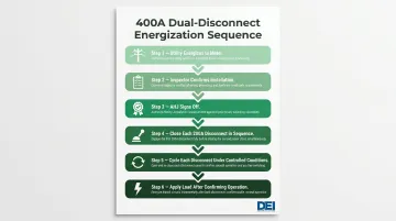
Energization Sequence
Follow the correct energization sequence:
- Utility energizes the service to the meter
- Inspector confirms installation
- AHJ signs off
- Facility team closes each 200A disconnect in sequence
- Test each disconnect by cycling it open and closed under controlled conditions
- Apply load only after both disconnects confirm proper operation
Correct Installation Indicators
- Balanced voltage readings at each disconnect's load terminals
- No ground fault indicators
- No abnormal heat at terminations after initial load application
Warning signs of problems:
- Asymmetric voltage readings
- Tripped breakers on first load
- Inspector rejection of grounding
Each symptom points to a different root cause — asymmetric voltage typically signals a conductor issue, tripped breakers suggest an overload or short, and grounding rejections almost always trace back to improper bonding at the service entrance.
Common Installation Problems and Fixes
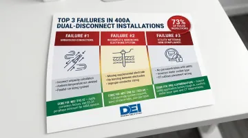
Undersized or Mismatched Service Conductors
Problem: Conductors are pulling excessive heat or failing ampacity requirements.
Likely cause: Conductor size was selected based on breaker rating alone rather than NEC Table 310.15(B)(16) ampacity adjusted for conduit fill, ambient temperature, and conductor bundling.
Fix: Recalculate conductor ampacity using the correct NEC correction and adjustment factors for the actual installation conditions. Upsize conductors as needed before energizing.
Improper or Incomplete Grounding Electrode System
Problem: AHJ rejects the installation at inspection due to grounding deficiencies, or ground fault events occur after energization.
Likely cause: Insufficient number of ground rods, improper spacing between rods, undersized grounding electrode conductors, or neutral-to-ground bonding completed downstream rather than at the service entrance.
According to Delta Wye Electric, 73% of failed commercial electrical inspections trace back to five common violations, including improper bonding of metallic systems and missing equipment grounding conductors.
Fix: Review NEC 250.52 and 250.66, install additional ground rods at correct spacing, re-bond neutral at the correct location, and resize grounding conductors per code.
Utility Rejection Due to Metering Non-Compliance
This class of problem typically surfaces last — after the rest of the installation is complete — making it one of the most disruptive to fix.
Problem: Utility refuses to energize or requires costly rework after installation.
Likely cause: The meter socket or CT cabinet was installed without confirming the utility's specific metering requirements for 400A service. Many utilities require a specific socket type, jaw configuration, or CT ratio that was not coordinated upfront.
Fix: Always obtain the utility's service requirements document before purchasing metering equipment. If a CT cabinet was installed incorrectly, coordinate with the utility on acceptable modifications before re-submitting for connection.
Pro Tips for a Successful 400 Amp Dual-Disconnect Installation
Three areas consistently separate smooth 400A dual-disconnect installs from ones that drag into re-inspections and rescheduling.
Coordinate with the utility early. Service upgrade lead times can run several weeks and are the most common cause of delays on 400A installations. Get written confirmation of metering requirements, conductor entry specs, and cutover scheduling before finalizing the equipment order.
Source factory-listed equipment. Pre-engineered enclosures and switchboards with UL listings already in place reduce inspector friction, eliminate field configuration errors, and come with documentation that satisfies AHJ requirements faster. DEI Power's UL 891-certified switchboards can be custom-configured to dual 200A disconnect layouts with in-house engineering support, cutting the back-and-forth before inspections.
Document every step. Photograph all terminations before closing covers, log torque values, and retain the permit and inspection records. Ensure as-built labeling is clear at the service entrance. This protects the contractor at inspection and becomes essential for any future maintenance or service calls.
Frequently Asked Questions
How much does it cost to upgrade from 200 amp to 400 amp?
A 400A service upgrade typically covers utility connection fees, permits, CT metering cabinet, dual 200A disconnect or switchboard, service entrance conductors, conduit, and grounding materials. Commercial installations run higher than residential due to equipment specs and multi-day labor. Consult your local utility and a licensed electrical contractor for project-specific pricing.
What are the NEC guidelines for 400 amp service?
NEC 230.71(B) permits two to six service disconnects instead of a single main. NEC 230.79 governs service conductor sizing via Table 310.15(B)(16). NEC Article 250 establishes grounding and bonding requirements. All service equipment must be listed for service entrance use per NEC 230.66.
What size wire is required for a 400 amp service?
For a 400A service using two 200A disconnects, each 200A feed requires minimum conductor sizing per NEC Table 310.15(B)(16) at 75°C terminals: 3/0 AWG copper (200A) or 250 kcmil aluminum (205A). Actual sizing must account for conduit fill, ambient temperature correction, and conductor bundling per NEC 310.15.
Do you need a CT cabinet for a 400 amp service?
CT (current transformer) cabinets are typically required by utilities for services above 200A because the current is too high for self-contained metering. Requirements vary by utility and region. Always verify metering requirements with your local utility before purchasing equipment.
How many ground rods are required for a 400 amp service?
NEC 250.53(A)(2) requires a minimum of two ground rods unless a single rod tests below 25 ohms resistance to earth. Rods must be spaced at least 6 feet apart per NEC 250.53(A)(3), with the grounding electrode conductor sized per NEC Table 250.66—for 250 kcmil aluminum service conductors, that's 2 AWG copper or 1/0 AWG aluminum.
Can you have two 200 amp panels?
Yes. NEC 230.71(B) explicitly permits up to six service disconnects at the service entrance point, so two 200A disconnects feeding separate panels is a code-compliant configuration for a 400A service, provided both disconnects are grouped and properly labeled as the service disconnect means per NEC 230.72.