According to NFPA data, approximately 16,930 non-home fires annually involve electrical distribution equipment, with arcing involved in 46% of cases due to electrical failure or malfunction. These statistics underscore the critical importance of proper selection and installation.
This guide covers what UL Listed designation means specifically for main service panels, how to select the correct panel for the application, and how to install it correctly from site preparation through post-installation validation.
Key Takeaways
- UL Listed panels (UL 67 or UL 891) must carry the "Suitable for Use as Service Equipment" marking to qualify as service entrance equipment
- Installation requires a licensed electrician and must be coordinated with the local AHJ and utility before energizing
- Match panel to system voltage, available fault current (SCCR), and enclosure type before procurement
- Neutral bonding rules differ between service and non-service applications — incorrect bonding creates fire and shock hazards
- Before energizing, validate torque values, SCCR compliance, GFPE function, and NEC-required markings
What Makes a Main Service Panel "UL Listed"?
A UL Listed main service panel is a complete, standalone assembly that has been tested and evaluated by Underwriters Laboratories against a recognized safety standard — not just its individual components. At service entrances, where electrical failures carry the highest consequences, that difference in scope matters.
Governing UL Standards
Two primary UL standards govern main service panels:
| Standard | Scope | Typical Application | Key Testing Areas |
|---|---|---|---|
| UL 67 (Panelboards) | ≤600V, bus ratings up to 1,200A | Residential, light commercial, branch circuits | Thermal performance, short-circuit withstand, wire bending space |
| UL 891 (Switchboards) | ≤1,000V AC, bus ratings 800A–6,000A | Commercial, industrial, utility distribution | Thermal performance under load, short-circuit withstand |
UL 67's 13th Edition (published May 15, 2018; last revised August 15, 2025) governs panelboard construction requirements. UL 891 applies to the larger, floor-mounted switchboards used in more complex distribution systems.
The "Suitable for Use as Service Equipment" Marking
Not all UL Listed panels can be used at the service entrance. The panel must carry a specific marking: "Suitable for Use as Service Equipment." Per NEC 230.2 (2026 edition) and 230.66 (2023 edition), only equipment with this marking can legally serve as the main service disconnect.
That marking verifies the panel includes provisions for a main bonding jumper and meets service-entrance safety requirements. Panels marked "suitable only for use as service equipment" have a factory-bonded neutral-to-ground connection and cannot be used as sub-panels.
Understanding UL Designation Types
| Designation | Scope | Application | Installation Status |
|---|---|---|---|
| UL Listed | Complete product safety evaluation | Finished, standalone products | Ready for field installation |
| UL Recognized | Component-level evaluation | Parts within larger assemblies | Subject to "Conditions of Acceptability" |
| UL Classified | Specific property evaluation | Targeted hazards (fire resistance) | Limited scope of evaluation |
| UL Certified | Enhanced umbrella mark | Consolidates Listed, Recognized, Classified | Modern terminology |
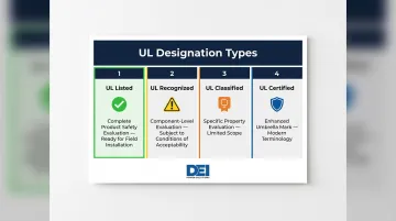
Only UL Listed (or UL Certified with "Listed" scope) panels are acceptable for main service applications. UL Recognized components and UL Classified products do not meet the complete safety evaluation required for service entrance equipment.
The Relationship Between UL Listing and NEC Compliance
UL standards govern panel construction; the NEC (Articles 230, 408) governs installation. A panel can be UL Listed but still fail inspection if installed incorrectly. Both requirements must be satisfied.
NEC 110.3(B) explicitly requires that "listed or labeled equipment shall be installed and used in accordance with any instructions included in the listing or labeling." This means manufacturer-specified torque values, wire bending space, and bonding provisions are code requirements, not suggestions.
Application Requirements: Selecting the Right UL Listed Panel
Selecting the correct panel before procurement prevents costly delays, change orders, and inspection failures. Four critical specifications must match the installation site conditions.
Voltage Configuration Matching
The panel's voltage rating must explicitly match the system configuration. Common U.S. commercial and industrial service voltage systems include:
| Configuration | Phase | Wire Count | Typical Application |
|---|---|---|---|
| 120/240V | Single-phase | 3-wire | Small commercial, split-phase |
| 208Y/120V | Three-phase | 4-wire (wye) | Most common commercial service; 120V plug loads, lighting |
| 480Y/277V | Three-phase | 4-wire (wye) | Larger commercial/industrial; 277V lighting, large HVAC |
| 240V / 480V Delta | Three-phase | 3-wire | Industrial motor loads (older facilities) |
The 208Y/120V configuration is the most common commercial building service in North America. The panel nameplate must explicitly call out the intended system voltage — a mismatch is an automatic rejection point during inspection.
Short-Circuit Current Rating (SCCR) Selection
SCCR is one of the most frequently overlooked specification errors in panel selection. NEC 110.10 requires that equipment have an SCCR sufficient to withstand fault current without extensive damage. NEC 408.6 (added in the 2020 NEC) states: "Switchboards, Switchgear, and Panelboards shall have a short-circuit current rating (SCCR) not less than the available fault current."
The panel's marked SCCR must meet or exceed the maximum available fault current at the point of installation. Using a panel with insufficient SCCR violates NEC Section 110.10 and creates a fault hazard where the panel could explode or ignite under fault conditions.
NEC 110.24 (since 2011) requires the maximum available fault current and calculation date to be field-marked on service equipment in other than dwelling units. A fault current study is required before specifying any panel.
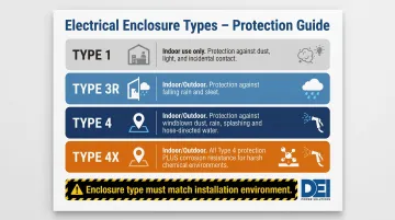
Enclosure Type Selection Based on Environment
NEC Section 110.28 and Table 110.28 govern enclosure selection based on environmental conditions:
| Enclosure Type | Location | Protects Against |
|---|---|---|
| Type 1 | Indoor only | Incidental contact, falling dirt |
| Type 3R | Indoor or outdoor | Rain, sleet, snow, ice formation |
| Type 4 | Indoor or outdoor | Splashing water, hose-directed water, windblown dust |
| Type 4X | Indoor or outdoor | Type 4 protections plus corrosive agents |
Installing a Type 1 (indoor) panel in an outdoor or wet location results in moisture ingress, corrosion, and immediate inspection failure. The enclosure type designation must match the installation environment.
Ground-Fault Protection of Equipment (GFPE) Requirement
NEC Section 230.95 requires GFPE for solidly grounded wye services of more than 150 volts to ground but not exceeding 1,000 volts phase-to-phase, where each service disconnect is rated 1,000 amperes or more.
This applies to most 480Y/277V services with disconnects rated 1,000A or higher. The panel must include provisions for GFPE devices and meet NEC 230.95(C) performance testing requirements (primary current injection testing with written records).
Exception: GFPE is not required for service disconnects serving continuous industrial processes where a nonorderly shutdown would introduce additional hazards.
The 2026 NEC expands this requirement to include DC systems exceeding 150V to ground.
Sourcing from Manufacturers with Engineering Support
For commercial and industrial projects with custom voltage, ampere rating, or layout requirements, sourcing panels from manufacturers that provide engineering documentation and configuration guidance reduces specification errors. DEI Power's UL 891-certified switchboards (400A-4000A) are manufactured in Ontario, California with BABA-compliant construction for federally funded projects. In-house engineering support covers configuration questions specific to your voltage, fault current, and jobsite requirements — reducing change orders before they reach the field.
Installing a UL Listed Main Service Panel: Complete Guide
Installation sequence matters. Steps performed out of order — especially around neutral bonding, grounding conductor landing, and conductor termination — create failures that won't surface during inspection but will generate fire and shock hazards over time.
Prerequisites and Safety Considerations
Before beginning any work:
- Confirm a licensed electrician will perform all installation work
- Obtain permits and AHJ approval before starting
- Coordinate with utility before connecting service entrance conductors
- Verify sufficient enclosure space and wire bending clearance per NEC Table 312.6(B)
- Confirm panel markings match system voltage and available fault current
- Verify panel is marked "Suitable for Use as Service Equipment" if used at service entry
Do not proceed if any of these conditions are unmet. The service entrance conductors remain energized even when the main disconnect is off and pose serious shock hazards without proper utility coordination.
Step-by-Step Installation
Mount and Position the Enclosure
Secure the cabinet to the appropriate structural surface. Confirm flush or surface mounting orientation per panel markings. Verify all knockouts used align with incoming conduit/raceway paths.
Maintain NEC-required working clearances per Article 110.26:
- Depth: Minimum 3 feet for 120/208V Condition 1 (Table 110.26(A)(1))
- Width: Minimum 30 inches or the width of the equipment, whichever is greater
- Height: Minimum 6 feet 6 inches from floor to ceiling or top of equipment
- Dedicated space: Equipment space extending from top of equipment to 6 feet or structural ceiling, whichever is greater
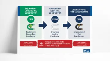
Land Conductors in Correct Sequence
Connect in this order:
- Equipment grounding conductor first (never leave this for last)
- Grounded (neutral) conductor second
- Ungrounded (hot) conductors third
Use only copper or aluminum wire as specified in the panel's markings. Torque all terminals to manufacturer-specified values marked on the wiring diagram. NEC 110.14(D) (2020 NEC) requires: "Tightening torque values for terminal connections shall be as indicated on equipment or in installation instructions provided by the manufacturer."
Improper torque is a leading cause of arcing faults. Over-torquing damages conductors; under-torquing creates high-resistance connections that heat under load.
Address Neutral Bonding Correctly Based on Application
For service equipment use: Install the main bonding jumper to bond the neutral bus to the enclosure as required by NEC Section 408.3(C). This creates the single bonding point required by NEC 250.28(D)(1).
For feeder or sub-panel applications: The neutral must remain fully isolated from the enclosure. NEC 250.142(B) explicitly prohibits using the grounded conductor for equipment grounding on the load side of the service disconnect.
Failure to isolate the neutral in non-service applications creates parallel current paths through equipment grounding conductors and metal enclosures, producing:
- Shock hazards from energized metal parts
- Fire hazards from localized heating at loose connections
- Objectionable current per NEC 250.6
- Interference with ground-fault protection systems
This is one of the most common and dangerous installation errors.
Install Main Disconnect and Branch Overcurrent Devices
Before installing overcurrent devices, confirm these requirements are met:
- No breaker or fuse exceeds the marked SCCR — devices with lower interrupting ratings than the panel's marked SCCR reduce the assembly's effective fault current rating, violating NEC 110.10
- Back-fed breakers are secured with required hold-down kits
- All unused openings are closed with filler plates per NEC Sections 110.12(A) and 408.7
Post-Installation Checks and Validation
With installation complete, verify the assembly before energizing. Work through these checks in sequence.
Visual Inspection Before Energizing
- Confirm all terminal torque values are met
- Verify all required markings are visible and legible from the front (voltage, current rating, SCCR, manufacturer identification)
- Confirm neutral bonding status matches the application (bonded for service, isolated for feeder)
- Check that no foreign material (metal shavings, debris) is present in the enclosure
- Verify unused openings are properly closed
Functional Testing
Test ground-fault protection of equipment (GFPE) if installed per NEC Section 230.95(C). A qualified person must perform this testing using primary current injection — the push-to-test button alone does not satisfy the requirement. Document results in writing and keep them available for the AHJ.
Verify the main disconnect functions correctly. Check that the "SERVICE DISCONNECT" label is placed adjacent to the disconnect handle as required by NEC Section 230.70(B) (2026 NEC).
Document all test results and retain them for the AHJ inspection record.
Common Installation Problems and Fixes
These three problems show up repeatedly during and immediately after main service panel installation — each one traceable to a step that gets skipped during pre-installation review.
Neutral Bonded in a Non-Service Location
Problem: The main bonding jumper is installed when the panel is used as a feeder or sub-panel, creating an unintentional bond between the neutral and enclosure at a load-side location.
This typically happens when a technician follows service panel installation habit or misreads the panel's bonding provisions markings.
Fix:
- Locate and remove the bonding screw or bonding jumper.
- Verify the neutral bus is mounted on an insulating support base.
- Confirm no parallel neutral path exists back to the service point.
- Test for objectionable current with a clamp meter on the equipment grounding conductor — any reading indicates the bonding error remains.
Installed Overcurrent Devices Exceed the Marked SCCR
Problem: Circuit breakers added during the project — individually or collectively — reduce the assembly's effective SCCR below the system's available fault current.
This occurs when breakers from different manufacturers or with lower interrupting ratings are installed without checking the panel's marking requirements for field-installed units.
Fix:
- Review panel markings for acceptable field-installed device designations.
- Replace non-compliant devices with listed breakers that match the panel's SCCR requirements.
- Verify all field-installed breakers are compatible with the panel's listed component specifications to maintain SCCR compliance.
- Retest and document compliance per NEC Section 110.10.
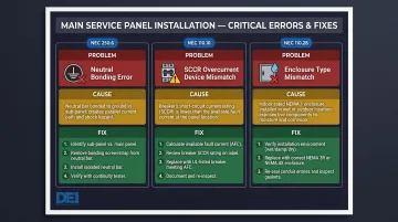
Enclosure Type Mismatch for the Installation Environment
Problem: A panel with a Type 1 (indoor) enclosure designation is installed in an outdoor or wet location, resulting in moisture ingress, corrosion, and inspection failure.
The panel was specified or procured without confirming the enclosure type against the installation environment — a spec review step that often gets bypassed under schedule pressure.
Fix:
- Replace the enclosure with one carrying the appropriate UL designation: Type 3R minimum for outdoor locations, Type 4 or 4X where wash-down or corrosion exposure exists.
- Confirm the replacement enclosure is compatible with the panel's UL Listing.
- Re-verify all conduit entries and sealing fittings meet the new enclosure type requirements.
DEI Power manufactures switchboards in both NEMA 1 (indoor) and NEMA 3R (outdoor weather-resistant) configurations, so the right enclosure can be specified from the start rather than corrected in the field.
Pro Tips for a Successful UL Listed Panel Installation
Panels missing required markings trigger field evaluations — adding cost and schedule risk. Before ordering, confirm the panel carries all of the following: "Suitable for Use as Service Equipment," SCCR value, voltage and current ratings, enclosure type designation, and wiring terminal torque markings. Missing any one of these can halt a project until a third-party evaluation is completed.
Coordinate energization sequence with utility and AHJ in writing. Document the order of operations, test results, and inspector sign-off in the project record before service conductors are connected. This documentation protects the contractor from rework liability and satisfies NEC Section 110.3(B) requirements.
Work with manufacturers that provide complete engineering documentation. For projects with federal or public funding requirements, confirm BABA-compliant manufacturing and verified configuration guidance before committing to a supplier. DEI Power manufactures UL 891-certified switchboards at their 50,000 sq. ft. Ontario, California facility with in-house engineering support and BABA-compliant construction — documentation that travels with the panel and reduces the change orders that come from under-specified equipment, with equipment often shipping within 1 business day.
Frequently Asked Questions
What is an UL listed electrical panel?
An UL Listed electrical panel is a complete assembly tested by Underwriters Laboratories and confirmed to meet the applicable safety standard (such as UL 67 for panelboards or UL 891 for switchboards). The UL Listed mark indicates the entire product — not just its components — has passed evaluation and is subject to ongoing factory surveillance.
What is the UL standard for electrical panels?
UL 67 is the primary standard for panelboards (600V or less, up to 1,200A bus), while UL 891 applies to low-voltage switchboards (up to 1,000V AC, 800A-6,000A bus). Both standards govern construction and safety requirements; the NEC governs how these panels must be installed.
What is the difference between UL 67 and UL 891?
UL 67 covers panelboards — typically used in residential, light commercial, and branch circuit applications. UL 891 covers low-voltage switchboards designed for larger power distribution in commercial, industrial, and utility applications, with higher ampere ratings and more complex bus configurations. Switchboards are typically floor-mounted; panelboards are wall-mounted.
Which is better, UL listed or UL certified?
"UL Certified" is the broader, updated term that encompasses UL Listed and UL Classified products under an Enhanced Certification Mark. For main service panels, UL Listed (or the equivalent UL Certified mark with "Listed" scope) is required — it confirms the complete product has been evaluated for all reasonably foreseeable hazards. The two marks are functionally equivalent for service entrance applications.
What not to touch in a breaker box?
Service entrance conductors remain energized even when the main breaker is off — never touch them without utility disconnection. The neutral bar and bus lugs should only be handled by a licensed electrician using appropriate PPE, following an electrically safe work condition per NFPA 70E Article 120.5.
What is a CSED panel?
A CSED (Combination Service Entrance Device) panel integrates the meter socket and main disconnect into a single enclosure, simplifying service entry installation. CSED units are tested under UL 67 and must carry the "Suitable for Use as Service Equipment" marking to qualify for service entrance installation.