Introduction
A 400 amp service entrance is where utility power connects to a building's electrical distribution system. Sizing wire for a 400A installation isn't straightforward — it involves calculating demand loads per NEC Article 220, choosing between copper and aluminum conductors, deciding between single conductors or parallel sets, and applying temperature and fill derating factors.
Getting those decisions wrong has real consequences. Undersized conductors create fire hazards and code violations. Oversized conductors waste thousands of dollars in unnecessary material costs.
Getting it right requires understanding the complete NEC sizing methodology — including the often-missed dwelling service allowance that can significantly reduce conductor requirements for residential 400A installations.
This guide walks through the complete wire sizing process:
- Calculating required ampacity
- Single vs. parallel conductor configurations
- Approved wire types for different installation methods
- Temperature and voltage drop adjustments
- Grounding electrode conductor requirements
- Common field mistakes that cause failures or expensive rework
Key Takeaways
- Standard approach: Two parallel sets of 250 kcmil aluminum (XHHW-2) or 3/0 AWG copper (THWN-2) per phase
- Start with NEC Article 220 load calculation, not the 400A equipment rating
- Size conductors to NEC Table 310.16's 75°C column unless terminals are confirmed 90°C-rated
- Residential 400A services may qualify for the 83% sizing allowance (400A × 0.83 = 332A required)
- Size the grounding electrode conductor separately per NEC Table 250.66, based on total conductor area
What Determines Wire Size for a 400 Amp Service Entrance?
The "400 amp" label on service equipment refers to the rated capacity of the switchboard or panel—not necessarily the load the system will actually carry. This distinction matters because the NEC requires sizing conductors based on calculated demand load per NEC Article 220, which accounts for diversity factors and realistic simultaneous usage patterns. In most installations, the calculated demand is substantially less than 400A.
The common mistake: Sizing conductors directly to 400A from the ampacity table without performing a load calculation first. This approach either wastes money on oversized wire or, if the 83% dwelling allowance is missed, results in non-compliant installations. The NEC explicitly prohibits this shortcut—NEC 230.42 requires service conductors to have ampacity sufficient for the loads calculated per Article 220, not simply matched to the service equipment nameplate.
NEC Table 310.16 and Temperature Ratings
NEC Table 310.16 is the primary ampacity reference for conductors in raceway, cable, or direct burial applications. The table lists ampacity values at three temperature ratings: 60°C, 75°C, and 90°C. A common error is defaulting to the highest ampacity column without checking terminal ratings.
NEC 110.14(C) requires using the lower of two temperature ratings:
- The conductor's insulation temperature rating
- The equipment terminal's temperature rating
Most service equipment lugs and terminals are listed at 75°C—not 90°C. Using the 90°C column without confirming terminal ratings is a code violation that can also cause premature terminal failure due to excessive heat. Always default to the 75°C column unless equipment documentation explicitly confirms 90°C-rated terminals.
The 83% dwelling service allowance is one of the most valuable and frequently overlooked provisions for residential 400A services. NEC 310.12 (NEC 2020 edition) permits dwelling unit service and feeder conductors for 120/240V, 3-wire, single-phase systems rated 100A through 400A to be sized at 83% of the service rating:
Calculation: 400A × 0.83 = 332A minimum conductor ampacity
This provision significantly changes final conductor selection: instead of needing conductors rated for 400A, you need conductors rated for 332A. The allowance applies specifically to single-family dwellings or individual dwelling units and cannot be used if adjustment or correction factors (for temperature or conductor bundling) are required.
Copper vs. Aluminum: Key Trade-offs
. Both must be sized from NEC Table 310.16 using the 75°C column and adjusted for actual conditions of use.
Conductor Size Options: Single Large Conductor vs. Parallel Sets
For 400A service, you face a structural choice: run one very large conductor per phase, or run two (or more) smaller conductors per phase in parallel. Industry practice strongly favors parallel sets because single large conductors are physically unwieldy and expensive to install.
Single Conductor Per Phase: Sizes and Limitations
To achieve 400A capacity with a single conductor per phase, you need approximately:
- Copper: 600 kcmil (420A at 75°C)
- Aluminum: 1000 kcmil (445A at 75°C)
At these sizes, single conductors create real jobsite problems:
- Extreme rigidity makes routing through conduit difficult, even with specialized pulling equipment
- Terminating 600–1000 kcmil conductors requires oversized lug kits that don't fit standard switchboard enclosures
- Multiple bends or tight working spaces compound the difficulty significantly
- Labor and equipment costs climb fast relative to parallel alternatives
Parallel Conductors: The Standard Approach
NEC 310.10(H) establishes strict paralleling requirements. All parallel conductors must be identical in:
- Conductor material (all copper or all aluminum)
- Circular-mil area (same gauge)
- Insulation type
- Length
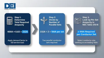
Step-by-step sizing calculation:
- Determine total required ampacity from Article 220 load calculation or 83% dwelling allowance
- For residential 400A: 400A × 0.83 = 332A minimum
- Divide by number of parallel sets (typically 2)
- 332A ÷ 2 = 166A per set
- Look up per-set ampacity in NEC Table 310.16 (75°C column)
- Need conductors rated ≥166A per set
The two conductor combinations below satisfy that 332A threshold and dominate residential 400A installs:
Most common residential 400A configurations:
| Configuration | Per-Set Ampacity | Combined Ampacity | Meets 332A? |
|---|---|---|---|
| Two sets of 250 kcmil aluminum (XHHW-2) | 205A | 410A | ✅ Yes |
| Two sets of 3/0 AWG copper (THWN-2) | 200A | 400A | ✅ Yes |
Commercial and industrial 400A services don't qualify for the 83% dwelling allowance, so they require the full 400A capacity. That typically means two sets of 500 kcmil aluminum or two sets of 250 kcmil copper per phase. Confirm your specific configuration with the authority having jurisdiction (AHJ) before finalizing conductor sizing.
Approved Wire Types for 400 Amp Service Entrance Installations
Wire "type" refers to the insulation designation — separate from wire "size." The installation method (conduit, direct burial, or overhead) determines which insulation types are code-approved for your application.
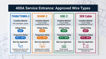
The four wire types you'll encounter most often on 400A service entrance work are summarized below:
| Wire Type | Insulation | Voltage | Temp Rating | Best For |
|---|---|---|---|---|
| THHN/THWN-2 | Thermoplastic (dual-rated) | 600V | 90°C dry / 75°C wet | Above-ground conduit (copper or aluminum) |
| XHHW-2 | Cross-linked polyethylene | 600V | 90°C dry and wet | Conduit, wet locations, underground; preferred for aluminum parallel sets |
| USE-2 | Cross-linked polyethylene | 600V–2000V | 90°C wet | Underground and direct burial; above-ground approved in some jurisdictions — confirm with the AHJ (Authority Having Jurisdiction) |
| SER Cable | Pre-jacketed assembly | Varies | Conductor-dependent | Overhead service drops; less practical for large parallel 400A runs due to assembly constraints |
Each type suits a specific installation method. Choosing the wrong one — for example, using THHN in a direct-burial application — creates a code violation even if the wire size is correct.
Practical installation guidance:
- Underground 400A service: XHHW-2 or USE-2 aluminum in conduit is the industry standard
- Above-ground in conduit: THWN-2 copper or XHHW-2 aluminum are standard choices
- Direct burial: USE-2 is specifically rated for this application
Critical Adjustments: Derating, Voltage Drop, and Utility Requirements
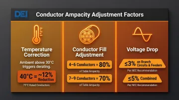
NEC Table 310.16 ampacity values assume specific baseline conditions: ambient temperature of 30°C (86°F) and no more than three current-carrying conductors in a raceway. When actual installation conditions differ, you must apply correction and adjustment factors that can substantially increase required conductor size.
Temperature correction factors: If ambient temperature exceeds 30°C—common in attics, rooftops, or southern climates—ampacity must be reduced per NEC 310.15(B) ambient temperature correction tables. For example, at 40°C ambient temperature, conductor ampacity is reduced by approximately 12% for 75°C-rated conductors.
Conductor fill adjustment factors: When more than three current-carrying conductors share a raceway, NEC 310.15(C) requires further ampacity reduction:
- 4-6 conductors: 80% of table ampacity
- 7-9 conductors: 70% of table ampacity
Voltage drop considerations: NEC 210.19(A) and 215.2(A) recommend limiting voltage drop to 3% on feeders and 5% combined for feeder plus branch circuits. These are Informational Notes, not mandatory requirements — but ignoring them risks equipment performance degradation from insufficient voltage.
Long service runs—common in commercial campuses, agricultural facilities, and industrial plants—may require upsizing conductors beyond ampacity table values to control voltage drop. The longer the run and the higher the load current, the more oversizing may be needed.
Utility company specifications: Utility requirements often exceed NEC minimums and can include:
- Specific meter base ratings and configurations
- CT (current transformer) metering requirements for services above 200A
- Service conductor entry specifications
- Conduit and weatherhead requirements
- Clearance and setback distances
These specifications must be confirmed with your local utility before finalizing conductor and equipment specifications. Once utility and NEC requirements are confirmed, load-side equipment must align with both. DEI Power's UL 891-certified 400A switchboards are built to standard service entrance configurations and can be custom-configured to your utility's specific metering, conduit, and clearance requirements.
Grounding and Conduit Sizing for 400 Amp Service
Two sizing decisions often trip up 400-amp service designs: the grounding electrode conductor (GEC) and the conduit. Both follow their own NEC rules, separate from the service conductor sizing covered above.
The GEC is sized using NEC Table 250.66, based on the area of the largest ungrounded service conductor — or the combined equivalent area for parallel sets.
Example calculation for parallel conductors: Two parallel 250 kcmil aluminum conductors per phase:
- 250 kcmil + 250 kcmil = 500 kcmil equivalent area
- Per NEC Table 250.66 for "over 250 kcmil through 500 kcmil" aluminum:
- Copper GEC required: 2 AWG
- Aluminum GEC required: 1/0 AWG
Conduit follows a different logic. Per NEC 310.10(H), each parallel set runs in its own conduit to maintain phase balance and equal impedance. Fill percentage is governed by NEC Chapter 9 and Annex C.
Conduit sizing example: For two 250 kcmil aluminum phase conductors plus one 250 kcmil neutral per conduit (3 conductors total):
- Minimum conduit size: 2-inch
- If a full-size ground conductor is included (4 conductors): 2.5-inch minimum
Larger conductors or additional neutrals typically push conduit to 3-inch or 3.5-inch. Use the NEC Chapter 9 tables and Annex C fill charts for your specific conductor type and the edition your jurisdiction has adopted — conduit fill requirements vary between THHN, XHHW-2, and other common service conductor insulations.
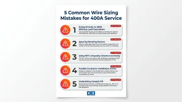
Common Wire Sizing Mistakes for 400 Amp Service
Sizing directly to 400A without a load calculation — Using the 400A service rating as the default conductor baseline, without an NEC Article 220 load calculation, leads to oversized conductors or a missed 83% demand allowance. The actual calculated demand is typically well below 400A, especially for residential services that qualify for that allowance.
Ignoring derating factors — Failing to apply ambient temperature correction or conductor fill adjustment factors when conditions exceed NEC Table 310.16 baseline assumptions. Inspectors frequently cite this violation during service entrance inspections, since conductors that look adequate per the ampacity table can be technically undersized once derating applies.
Using the 90°C ampacity column incorrectly — Selecting conductor size from the 90°C column without confirming all equipment terminals are rated for 90°C. NEC 110.14(C) requires using the lower temperature rating, and most service equipment lugs are listed at 75°C — making this a common termination failure point.
Parallel conductor installation errors — Running parallel sets with mismatched lengths, different insulation types, or unequal phase distribution violates NEC 310.10(H). Unequal impedances cause unbalanced current sharing, where one conductor exceeds its design load while the other runs underutilized.
Undersizing conduit fill — Calculating conduit size for phase conductors only, without accounting for the neutral and ground, produces a conduit that's too tight to pull wire through. This error typically surfaces after the conduit is already installed, requiring a full replacement.
Frequently Asked Questions
Can I get a 400 amp service for my house?
Yes, 400A residential service is permitted under the NEC and covered by NEC 310.12 dwelling service sizing provisions. It's typically reserved for large homes with heavy electrical demand—multiple EV chargers, large HVAC, pools, or workshops. You'll need utility approval, a building permit, an Article 220 load calculation, and a licensed electrician.
What are the NEC requirements for a 400 amp service entrance?
Key NEC requirements cover four areas:
- Article 220: Load calculation to determine conductor ampacity
- Table 310.16: Conductor sizing with correct temperature column
- Article 230: Service disconnect location, ratings, and labeling
- Article 250: Grounding electrode system
Local AHJ and utility requirements often exceed NEC minimums—confirm both before finalizing your design.
What size conductor is required for a 400 amp service entrance?
The most common configuration for residential 400A services using the 83% dwelling allowance is two parallel sets of 250 kcmil aluminum (XHHW-2 or USE-2) or two parallel sets of 3/0 AWG copper (THWN-2) per phase. Commercial or industrial services without the dwelling allowance require larger conductors—often two sets of 500 kcmil aluminum or 250 kcmil copper per phase. Always verify with an Article 220 load calculation and confirm with your local AHJ.
Can 500 kcmil conductors or parallel 3/0 copper be used for a 400 amp service entrance?
Yes, with the right configuration. A single 500 kcmil aluminum conductor per phase rates at 310A at 75°C—short of 400A—so parallel sets are required. Two parallel 3/0 AWG copper conductors per phase (200A × 2 = 400A) is a standard residential approach under the 83% dwelling allowance. Verify all configurations against load calculations, terminal temperature ratings, and applicable derating factors.
What size conduit is required for a 400 amp service entrance?
Conduit size depends on conductor size, count, and insulation type. For parallel 250 kcmil aluminum sets with a neutral, 2-inch to 2.5-inch conduit per run is typical for three conductors; a full-size ground bumps that to 2.5-inch minimum. Calculate exact sizing using NEC Chapter 9 fill tables and Annex C for your specific configuration.
Is a 400 amp service typically single-phase or three-phase, and does 480V require a 3- or 4-wire configuration?
Residential 400A services are typically single-phase (120/240V). Commercial and industrial installations most often use three-phase configurations. 480V three-phase services can be 3-wire delta (three hot conductors, no neutral) or 4-wire wye (480Y/277V with neutral, providing both 480V three-phase and 277V single-phase). The configuration depends on connected equipment requirements and utility supply—confirm with both utility and AHJ before specifying.