Introduction
Service entrance equipment is the boundary where utility power meets a building's internal electrical system. It encompasses the complete assembly of conductors, meters, disconnects, and panels that deliver electricity from the utility grid to every circuit in a facility.
For contractors, engineers, and facility teams, getting this system right is critical. The service entrance is the single point of failure that — if improperly sized or installed — can cause facility-wide outages, failed inspections, or serious safety hazards.
A common source of confusion: where does the utility's scope end and customer responsibility begin? NEC Article 230 defines the "service point" — the legal and technical boundary between utility-owned infrastructure and customer-owned equipment — but its exact physical location varies by utility territory and service type.
This guide covers:
- What service entrance equipment is and how it's defined
- Core components of a complete service entrance assembly
- Overhead vs. underground service conductor types
- NEC Article 230 compliance requirements
- How responsibility divides between the utility and the customer
Key Takeaways
- Service entrance equipment connects utility power to a building's internal wiring through the service drop/lateral, meter, main disconnect, and distribution panel
- Conductors arrive overhead via service drop or underground via service lateral — each method has distinct cable types and installation requirements
- NEC Article 230 governs clearances, grounding, disconnect placement, and wiring methods for all service entrance installations
- Utilities own and install the service drop; customers are responsible for the meter base, weatherhead, conduit, main disconnect, and downstream distribution equipment
- Switchboards and distribution equipment downstream of the main disconnect must be rated for the system's voltage, amperage, and fault current
What Is Service Entrance Equipment?
Per NEC Article 100, service equipment is "the necessary equipment, usually consisting of a circuit breaker(s) or switch(es) and fuse(s) and their accessories, connected to the load end of service conductors to a building or other structure, or an otherwise designated area, and intended to constitute the main control and cutoff of the supply." This definition covers everything from the point where utility lines meet the building through to the main disconnect or service panel.
The service point is defined as "the point of connection between the facilities of the serving utility and the premises wiring" — essentially the demarcation between utility and customer ownership. This boundary determines who installs, owns, and maintains each component of the service entrance system. Many contractors misunderstand this boundary, leading to disputes over responsibility and installation scope.
Overhead vs. Underground Delivery
Service entrance equipment uses one of two delivery methods:
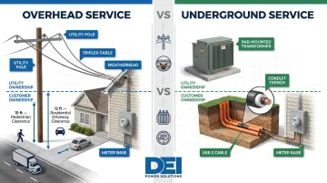
Overhead service: Conductors run from a utility pole to a weatherhead mounted on the building via a service drop. The utility installs and owns the service drop conductors. Overhead services require minimum clearance heights per NEC 230.24: 10 ft at building entrances, 12 ft over residential driveways (up to 300V), and 18 ft over public streets.
Underground service: Conductors run from a pad-mounted transformer to the meter base via a service lateral buried in conduit or direct-burial cable. The customer typically installs the trenching and conduit on their property, while the utility furnishes the lateral conductors.
The delivery method drives cable selection, conduit routing, and code compliance requirements — all of which feed directly into how the service entrance equipment is configured.
Residential vs. Commercial/Industrial Service
Residential service entrance equipment typically consists of a 120/240V single-phase service rated 100A to 200A, with a simple meter base and load center.
Commercial and industrial facilities require substantially more. Common configurations include:
- 480V three-phase systems rated 400A to 4000A
- Multiple metering points for tenant or departmental billing
- Complex disconnect arrangements to meet NEC Article 230 limits on service disconnecting means
- Robust switchboard assemblies rated for available fault current and load distribution across critical systems
The service entrance is the facility's single point of power entry — which means improper sizing, inadequate fault protection, or code violations can trigger failed inspections, insurance denials, or unplanned downtime. In mission-critical environments like data centers, healthcare facilities, and manufacturing plants, those consequences compound fast.
Main Components of Service Entrance Equipment
Service Drop or Service Lateral
The service drop consists of overhead conductors running from the last utility pole to the weatherhead on the building. These are typically triplex cables (two insulated hot conductors plus one bare neutral) rated for outdoor exposure. The utility installs and owns these conductors.
The service lateral consists of underground cables running from a pad-mounted transformer to the meter base. These cables must be rated for direct burial (such as USE-2) or installed in conduit. The customer typically installs the conduit system on their property, while the utility furnishes the lateral conductors themselves.
Weatherhead and Service Mast
The weatherhead is the curved conduit fitting at the top of the service mast that prevents water from entering the conduit. NEC 230.54 requires service raceways to be equipped with a raintight service head at the point of connection to overhead service conductors. The weatherhead must be located above the point of attachment, with exceptions permitting up to 24 inches below if impracticable.
The service mast provides the structural support for overhead service conductors. NEC requires adequate mast strength to support conductor weight and wind loads. Drip loops must be formed on individual conductors to direct water away from the service raceway and equipment.
Electric Meter and Meter Base
The meter measures electrical consumption in kilowatt-hours and serves as the metering demarcation point between utility and customer for billing purposes. The meter base (also called a meter socket) is a customer-furnished enclosure that must be securely mounted, weatherproof (typically NEMA 3R rated), and sized to match the service amperage. UL 414 covers meter sockets for use with watthour meters and test switches.
According to PG&E's Greenbook Manual, the meter base is customer-owned and customer-maintained, while the meter itself is utility-owned.
Main Disconnect
The main disconnect is a circuit breaker or switch that simultaneously disconnects all ungrounded conductors from the utility supply. NEC 230.70 requires a readily accessible disconnect either outside the building or inside nearest the point of entrance. A significant code change occurred in the 2020 NEC: Section 230.71 now requires **each service to have only one disconnecting means**, replacing the decades-old allowance for up to six disconnects in a single enclosure. Four specific configurations under 230.71(B) remain permitted, including switchboards with one disconnect per separated vertical section.
Service Panel or Switchboard
The service panel (for residential and light commercial) or switchboard (for larger commercial and industrial facilities) receives power from the main disconnect and distributes it to branch circuits throughout the building. For commercial and industrial projects, this equipment must be UL-listed and properly rated for voltage, amperage, and short-circuit current.
UL 891 is the standard for dead-front switchboards rated 600V or less — the most common certification for switchboards in North American commercial and industrial applications. Dead-front construction keeps live parts enclosed and inaccessible during normal operation.
DEI Power's UL 891-certified switchboards are built for this downstream distribution role using Siemens components. Key specifications include:
- Amperage range: 400A to 4000A
- Voltage configurations: 480V, 480Y/277V, 208Y/120V, and others
- Enclosure options: NEMA 1 (indoor) or NEMA 3R (outdoor/weather-resistant)
- Applications: Commercial buildings, industrial plants, data centers, and utility infrastructure
Grounding and Bonding System
The grounding electrode system provides a low-resistance path to earth, stabilizing voltage levels and enabling overcurrent protection devices to function correctly during fault conditions. NEC Table 250.66 specifies grounding electrode conductor (GEC) sizing based on service conductor size:
| Service Conductor Size (Cu) | Service Conductor Size (Al) | Min. GEC Size (Cu) | Min. GEC Size (Al) |
|---|---|---|---|
| 2 AWG or smaller | 1/0 AWG or smaller | 8 AWG | 6 AWG |
| 2/0 or 3/0 AWG | 4/0 or 250 kcmil | 4 AWG | 2 AWG |
| Over 350 thru 600 kcmil | Over 500 thru 900 kcmil | 1/0 AWG | 3/0 AWG |
| Over 1100 kcmil | Over 1750 kcmil | 3/0 AWG | 250 kcmil |
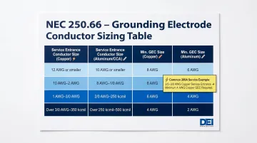
For a typical 200A service using 2/0-3/0 AWG copper conductors, the required GEC is 4 AWG copper. Grounding electrodes may include ground rods, water pipe connections, or concrete-encased electrodes (Ufer grounds).
Types of Service Entrance Conductors and Cables
NEC defines two distinct categories of service entrance conductors: service drop conductors (overhead, from the utility's last support to the service point) and service entrance conductors (from the service point into the building to the first disconnect). These terms have different installation requirements and must not be confused.
Overhead vs. Underground Conductors
Overhead service drop conductors are typically triplex cable rated for outdoor exposure. They must meet minimum clearance heights per NEC 230.24(B):
- 10 ft minimum at building entrances and pedestrian areas
- 12 ft over residential driveways and commercial areas (up to 300V to ground)
- 15 ft over the same areas when voltage exceeds 300V to ground
- 18 ft over public streets, alleys, and parking areas subject to truck traffic
Underground service lateral conductors must be rated for direct burial or installed in conduit. USE-2 cable is the standard choice: rated for 90°C in wet and dry locations, it carries UL 854 certification and uses moisture-resistant insulation suited for continuous underground exposure.
Conductor sizing must account for voltage drop over longer runs, not just ampacity requirements.
SER vs. SEU Cable: Key Differences
| Characteristic | SER Cable | SEU Cable |
|---|---|---|
| Full name | Service Entrance Round (Style R) | Service Entrance Unarmored (Style U) |
| Cross-section | Round | Flat (oval) |
| Conductor count | 3 or 4 insulated + bare ground | 2 insulated + bare concentric neutral |
| Ground wire | Separate bare ground conductor | Concentric neutral wires serve as neutral (no separate ground) |
| Primary application | Feeders to sub-panels, 3-phase loads | Service entrance: meter to main panel |
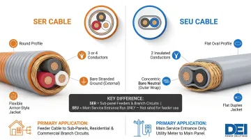
The key practical distinction: SER can serve both as the main service cable and as a downstream feeder to sub-panels or large appliances. SEU is limited to the main service run between weatherhead and meter/panel — it's common in older installations but unsuitable for feeder work due to its missing separate ground.
Both types fall under NEC Article 338 and must use AA-8000 series aluminum alloy conductors per NEC 310.14.
Conductor Material: Aluminum vs. Copper
Most service entrance cables use aluminum alloy (AA-8000 series) conductors because aluminum is significantly less expensive and lighter than copper at the heavy gauges required for service entrance applications.
For a standard 200A service:
- Aluminum: 4/0 AWG (rated 180A at 75°C)
- Copper: 3/0 AWG (rated 200A at 75°C)
For larger commercial services, typical aluminum conductor sizes include:
- 400A service: Two parallel sets of 250 kcmil Al
- 600A service: Two parallel sets of 350 kcmil Al
- 800A service: Three parallel sets of 300 kcmil Al or two sets of 500 kcmil Al
Antioxidant compound at aluminum terminations: The NEC does not require antioxidant compound on aluminum conductor terminations. During 2023 NEC development, Code Making Panel 1 explicitly denied a proposal to mandate it, stating "Aluminum conductors do not always require use of an anti-oxidant at terminations."
That said, antioxidant should be applied if the connector manufacturer recommends it. When manufacturer instructions require it, those instructions must be followed per NEC 110.3(B) — the compound is not a blanket code requirement, but it may still be a product requirement.
NEC Code Requirements for Service Entrance Equipment
For any service entrance installation, NEC Article 230 is the primary governing standard. It covers:
- Number of service conductors permitted per building
- Minimum insulation and conductor requirements
- Clearance and height rules
- Disconnect placement
Key NEC 230 Requirements for Commercial and Industrial Projects
NEC 230.2 – Number of Services: A building or structure shall be supplied by only one service, with exceptions for:
- Fire pumps, emergency systems, legally required standby systems
- Multiple-occupancy buildings with no shared accessible service area
- Capacity requirements exceeding 2000A at 600V or less
- Different characteristics (voltages, frequencies, phases, or rate schedules)
NEC 230.40 – Number of Service-Entrance Conductor Sets: Each service drop or lateral shall supply only one set of service-entrance conductors, with five specific exceptions for grouped disconnects, multiple occupancies, and dwelling configurations.
NEC 230.43 – Permitted Wiring Methods (up to 1000V): The 2020 NEC lists 20 permitted wiring methods for service-entrance conductors, including:
- Rigid metal conduit (RMC)
- Intermediate metal conduit (IMC)
- Electrical metallic tubing (EMT)
- Service-entrance cables (Types SE, USE, USE-2)
- Wireways and busways
- Type MC cable and mineral-insulated cable (Type MI)
- Rigid PVC conduit, HDPE conduit, and liquidtight flexible conduit
UL Listing Requirements
All service entrance equipment components — cables, meter bases, disconnects, and distribution panels — must be UL-listed for their intended application per NEC 110.2 and 110.3. UL 854 covers Type USE, USE-2 (below-ground), and Type SE (above-ground) power cables rated 600V for installation per NEC Article 338. Specifying listed equipment is required for AHJ inspection approval and insurance compliance.
For switchboards used in downstream distribution, UL 891 certification verifies that dead-front switchboard assemblies are designed and manufactured to safely manage and distribute electrical power at 600V or less. The UL 891 General Coverage Program allows approved manufacturers to apply the UL Mark at their factories for custom-built switchboards without submitting complete product samples. This reduces approval delays and simplifies compliance for custom commercial and industrial applications.
Who Is Responsible for Service Entrance Equipment — and What Comes Next?
Division of Responsibility
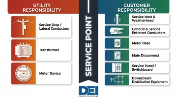
The utility (power supplier) furnishes and installs:
- Service drop conductors (overhead) or service lateral conductors (underground)
- Transformer
- Meter (the device itself)
The customer (property owner or contractor) is responsible for furnishing and installing:
- Service mast and weatherhead
- Service entrance conduit and conductors from the service point into the building
- Meter base (meter socket)
- Main disconnect
- Service panel or switchboard
- All downstream distribution equipment
This boundary is defined by the service point. According to PG&E's Greenbook Manual (2026 edition), PG&E's maintenance boundary for overhead service "begins at the point of attachment (i.e. connections at the weather head) and into the applicant's building." For underground service, it "begins at termination point in the panel and into the applicant's building."
Downstream Distribution Equipment
Once power passes through the main disconnect, it must be distributed safely through code-compliant switchboards, panelboards, or other distribution equipment. For commercial, industrial, and utility-scale projects, this downstream equipment must be correctly rated for:
- Voltage: 480V, 480Y/277V, 208Y/120V, or other system voltages
- Amperage: Adequate bus rating and breaker capacity for connected loads
- Short-circuit current: Adequate interrupting rating for available fault current at the installation location
DEI Power manufactures UL 891-certified low-voltage switchboards built specifically for this downstream distribution role. These switchboards are available in ratings from 400A to 4000A, with custom configurations for commercial buildings, data centers, industrial plants, and utility substations — built with Siemens components in NEMA 1 (indoor) or NEMA 3R (outdoor) enclosures.
For federally funded utility and public infrastructure projects, DEI Power also offers BABA-compliant switchboards. Engineering support is available to help contractors and engineers correctly specify downstream equipment before procurement.
Ongoing Maintenance Responsibility
Once installed and energized, ongoing maintenance of service entrance equipment — weatherhead, meter base, conduit, service panel — is the property owner's or facility team's responsibility. Utilities maintain only their conductors up to the service point.
Regular inspection of customer-side components is essential for preventing unplanned outages, corrosion-related failures, and safety hazards. PG&E's Greenbook reserves the right to access company facilities on the applicant's premises at any time for inspection, meter reading, routine maintenance, and emergency work.
Frequently Asked Questions
What is considered service entrance equipment?
Service entrance equipment includes all conductors and hardware used to deliver power from the utility system to a building's wiring — covering the service drop or lateral, meter, main disconnect, and service panel or switchboard, per NEC Article 100.
What are some functions of service entrance equipment?
Service entrance equipment receives power from the utility supply, measures consumption via the meter for billing, and distributes power to branch circuits through overcurrent protection devices.
What is a CSED device?
A CSED (Combination Service Entrance Device) combines the meter socket, main disconnect, and sometimes branch circuit breakers into one enclosure. It's common in residential applications and increasingly used in light commercial settings to simplify installation and save space.
What's the difference between SER and SEU?
SER cable includes a separate bare ground wire, making it suitable for feeder runs beyond the main panel. SEU cable does not include a separate ground and is typically limited to the main service run between the weatherhead and the meter or service panel.
What are the two different types of service entrance conductors?
Overhead service drop conductors run from a utility pole to the weatherhead. Underground service lateral conductors run from a pad-mounted transformer to the meter base. Each type carries different cable ratings, burial or clearance requirements, and NEC installation rules.
Who is responsible for the service entrance cable?
Service drop conductors from the utility pole are installed and owned by the utility company. Service entrance conductors on the building side of the service point — including the weatherhead, conduit, and meter base connections — are the responsibility of the property owner or licensed electrical contractor.