Introduction
In commercial, industrial, and data center power distribution, 240/415V is a three-phase system that delivers two distinct usable voltages from a single transformer configuration: 240V for single-phase loads and 415V for three-phase equipment. This dual-voltage architecture shapes how electrical infrastructure is sized, protected, and operated at every level.
For engineers, contractors, and facility teams making specification decisions, understanding what these voltages represent, how they mathematically relate, and where their operating boundaries lie is essential to avoiding costly misapplication.
The consequences of misidentifying which voltage applies to a given load—line-to-neutral versus line-to-line—are among the most serious errors in 240/415V design. Equipment rated for 240V connected across 415V experiences approximately 73% overvoltage, triggering immediate failure or rapid degradation. Meanwhile, systems designed for 415V operation but subjected to sustained undervoltage face motor torque loss, transformer saturation, and efficiency penalties that accumulate invisibly until threshold failures occur.
Getting this right starts with the fundamentals—voltage relationships, tolerance standards, and where field mistakes most commonly occur.
Key Takeaways
- 240/415V is a three-phase, four-wire Wye system: 240V line-to-neutral, 415V line-to-line, related by a factor of √3
- Increasingly adopted in North American data centers, delivering 4–5% efficiency gains over 208V systems
- Classified as Low Voltage under ANSI C84.1 (≤1000V)—not medium voltage despite exceeding conventional 208V systems
- Equipment must tolerate full utility tolerance bands (typically ±5–10%), not just nominal values
- Mixing up L-N (240V) and L-L (415V) during load specification leads to immediate or accelerated equipment failure
What 240/415V Represents in Power Distribution
240/415V is a three-phase, four-wire Wye (star) distribution system formally designated as 415Y/240V. The notation indicates 240V phase-to-neutral voltage and 415V phase-to-phase (line-to-line) voltage produced when measuring across any two phase conductors. This dual-voltage capability is a fundamental design characteristic, not a derived property—it originates from the transformer secondary winding configuration that generates both voltages simultaneously.
The mathematical relationship is fixed by three-phase geometry. In any balanced Wye system, line-to-line voltage equals line-to-neutral voltage multiplied by the square root of three (√3, approximately 1.732). Applied to this system:
240V × 1.732 = 415.68V, rounded to the nominal 415V designation.
This derivation is documented in detail by Relay Training's guide to the square root of three in power calculations. The √3 multiplier comes directly from the 120-degree phase separation between conductors — a fixed geometric property of three-phase systems.
That fixed math, however, describes nominal behavior under ideal conditions. In real installations, actual delivered voltage fluctuates with load, conductor impedance, and utility regulation — which is why engineers treat 240/415V as both a transformer output specification and a variable they must actively manage when selecting equipment ratings and protection settings.
Factors That Influence Actual Delivered Voltage
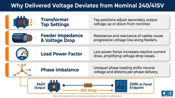
Nominal 240V/415V values assume balanced loading, negligible feeder impedance, and a steady utility supply. In practice, several factors push delivered voltage away from these ideal values:
- Transformer tap settings: Adjusted to compensate for upstream transmission voltage variations, typically in ±2.5% or ±5% increments
- Feeder impedance and voltage drop: Conductor resistance (I²R losses) and reactance (inductive drop) reduce voltage proportionally to current magnitude and distance
- Load power factor: Low power factor increases current for the same delivered power, amplifying voltage drop across distribution conductors
- Phase imbalance: Unequal loading across the three phases shifts neutral voltage and creates asymmetry in line-to-neutral voltages at endpoints
A 240/415V system operating at 90% load with 0.85 power factor may deliver 230V line-to-neutral at panel endpoints despite transformer secondary output measuring 242V. Engineers must size conductors and select tap settings to maintain voltage within tolerance under worst-case loading scenarios.
Operating Voltage Range and Tolerance Limits
Voltage tolerance standards govern the acceptable deviation range for utility-supplied systems. Equipment must operate reliably across the full tolerance band—not just at the nominal value—to avoid performance degradation or failure during routine voltage fluctuations.
Nominal Operating Range
The 240V line-to-neutral and 415V line-to-line designations represent midpoint values under balanced load conditions with proper transformer configuration and utility voltage within normal service limits. These values serve as reference points for equipment ratings, but actual field measurements will vary within defined tolerance bands.
ANSI C84.1-2020 establishes two voltage ranges for North American applications:
- Range A (Normal Conditions): Continuous operating range where equipment must deliver rated performance
- Range B (Contingency Conditions): Short-term acceptable deviation during abnormal utility supply or system fault conditions
For 240V line-to-neutral service, ANSI C84.1 specifies:
| Parameter | Range A | Range B |
|---|---|---|
| Service Voltage | +5% / -5% (252V max / 228V min) | +5.8% / -8.3% (254V max / 220V min) |
| Utilization Voltage | +5% / -10% (252V max / 216V min) | +5.8% / -13.3% (254V max / 208V min) |
Applying the √3 multiplier yields corresponding line-to-line boundaries: Range A service at 415V nominal spans approximately 436V maximum to 395V minimum; Range A utilization spans 436V maximum to 374V minimum.
Allowable Tolerance and Boundary Limits
Equipment designers must account for the full Range A band for continuous operation. Range B exposure is permissible during contingencies but may result in reduced performance, accelerated component stress, or protective device activation.
Service voltage applies at the utility meter or service entrance; utilization voltage applies at the equipment terminals after accounting for distribution system voltage drop. The wider utilization tolerance reflects real-world voltage loss through building feeders and branch circuits.
Safe Operating Margin
Equipment rated for 415V operation is tested to withstand voltages above nominal to handle transient overvoltages (switching surges, capacitor bank energization, lightning-induced transients) without damage or nuisance tripping. IEEE C57.12.00-2006 specifies that transformers must operate continuously at 105% rated voltage at full load and 110% rated voltage at no load. Exceeding these limits drives core saturation, pushing magnetizing current more than 5x above normal and accelerating insulation degradation.
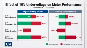
The lower boundary carries its own risks. NEMA MG 1 Part 12 confirms motor torque is proportional to voltage squared: a 10% voltage drop yields approximately 19% torque reduction (0.90² = 0.81), with 11% current increase and 23% temperature rise in high-efficiency motors. Operating near tolerance limits compounds stress on insulation, bearings, and thermal management systems.
Key Technical Properties of 240/415V Systems
Three characteristics define 240/415V system behavior: Wye configuration geometry, power delivery capacity, and interaction with harmonic loads. These properties determine equipment selection, conductor sizing, and protection coordination requirements.
Property 1: Wye Configuration and Phase Geometry
The four-wire Wye configuration provides two distinct usable voltages from a single transformer secondary. This is a key advantage over three-phase Delta systems, which cannot provide a neutral reference for single-phase loads. In a Wye system:
- 240V single-phase loads connect line-to-neutral (one phase conductor and the neutral)
- 415V three-phase loads connect line-to-line (across any two phase conductors)
Phase conductors are separated by 120 electrical degrees. This geometry produces the √3 relationship between line-to-neutral and line-to-line voltages. Load balance across all three phases is critical: when phase currents are equal in magnitude and 120° apart, they cancel in the neutral conductor, keeping neutral current near zero.
Unbalanced loading (common when single-phase loads dominate) causes neutral current flow equal to the phasor sum (vector sum) of phase currents. This creates voltage asymmetry across the three phases and degrades voltage regulation across the system. Neutral conductor sizing must account for worst-case unbalance scenarios.
Property 2: Power Capacity and Delivery Efficiency
A 240/415V system delivers significantly more power than lower-voltage alternatives at the same amperage. At 200A:
- Single-phase power per phase: 200A × 240V = 48 kVA
- Total three-phase power: √3 × 415V × 200A ≈ 144 kVA
Compare this to a 208Y/120V system at 200A:
- Total three-phase power: √3 × 208V × 200A ≈ 72 kVA
The 415V system delivers approximately 2x the apparent power at identical current levels.
Higher voltage also reduces I²R losses in conductors. Equipment operating at 415V draws proportionally less current for the same power output compared to 208V operation. The practical result:
- Smaller conductor cross-sections for the same power capacity
- Reduced heat generation in distribution infrastructure
- Lower voltage drop over equivalent feeder lengths
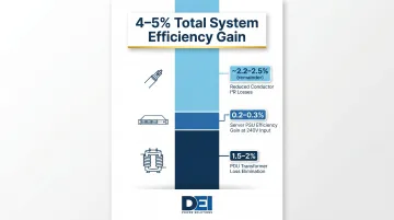
Data center efficiency studies document 4-5% total system efficiency gains from 415V distribution compared to 208V. The improvement breaks down as:
- 1.5-2% PDU transformer loss elimination (when using 415V/240V directly without step-down transformation)
- 0.2-0.3% server power supply efficiency gain at 240V input versus 208V input
- Reduced conductor losses due to lower current flow
For projects where these efficiency gains matter, switchgear selection must match the system voltage and load profile. DEI Power's UL 891-certified low-voltage switchboards support 240/415V configurations from 400A to 4000A in NEMA 1 (indoor) and NEMA 3R (outdoor) enclosures.
Property 3: Interaction with Load Types and Harmonic Effects
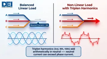
Non-linear loads (variable frequency drives, switch-mode power supplies in servers, LED drivers) generate harmonic currents that distort the sinusoidal waveform. In a four-wire Wye system, triplen harmonics (3rd, 9th, 15th order) behave differently than other harmonic orders.
Triplen harmonics are zero-sequence, meaning they have zero phase displacement across all three phase conductors. Unlike positive-sequence (1st, 7th, 13th) and negative-sequence (5th, 11th) harmonics that cancel in the neutral, triplen harmonics add arithmetically in the neutral conductor.
In a balanced linear load, neutral current is zero. In a balanced non-linear load rich in triplen harmonics, neutral current can exceed phase conductor current. This requires:
- Neutral conductor sizing equal to or greater than phase conductors in harmonic-heavy installations
- Derating of transformers serving non-linear loads (K-factor rated transformers)
- IEEE 519-2014 voltage distortion limits: individual harmonics ≤3%, total harmonic distortion (THD) ≤5%
The 240/415V system enables higher power density and efficiency, but neutral conductor specification must account for harmonic accumulation — a detail frequently missed when migrating from Delta or 208V Wye systems.
How 240/415V Power Systems Are Specified and Validated
Specifying a 240/415V system correctly means locking down system parameters before equipment procurement — then confirming those parameters in the field before energization and under operating load.
Specification and Documentation Requirements
Complete design documentation for 240/415V systems must include:
- 415Y/240V nominal voltage designation
- System frequency: 50 Hz or 60 Hz, depending on region
- Prospective short-circuit current at the point of supply — required for protective device coordination and equipment withstand ratings
- Continuous current ratings per circuit and per phase
- Neutral sizing multiplier for harmonic-rich loads (typically 1.0x to 2.0x phase conductor size, depending on harmonic content)
- Equipment ratings and certifications: UL 891 listing, voltage rating tolerance, and fault current withstand (AIC or kA rating)
For North American installations, distribution equipment must comply with NEC Article 408 (Switchboards and Panelboards) and carry UL 891 listing.
DEI Power's UL 891-certified switchboards are available in 415/240V configurations from 400A to 4000A, assembled with OEM Siemens components at their 50,000 sq. ft. facility in Ontario, California. Custom configurations cover neutral sizing, conductor ratings, and protection coordination for harmonic-heavy data center and industrial applications.
Measurement and Verification Methods
Once documentation is complete, field verification requires instruments accurate under harmonic distortion and properly rated for the electrical environment safety category.
Required instruments:
- True-RMS voltmeters — measure line-to-neutral and line-to-line voltages accurately regardless of waveform distortion; average-responding meters misread harmonic-rich voltages
- Power quality analyzers — capture voltage THD, individual harmonic magnitudes, and phase angle relationships
- True-RMS clamp meters — verify phase current balance and neutral current magnitude
Instrument selection doesn't end at accuracy. The safety category rating of your meter determines whether it can safely survive a transient overvoltage event on a 415V circuit.
Safety ratings — critical for 415V systems:
IEC 61010-1 defines measurement categories by electrical environment:
| Category | Application | Required for 415V |
|---|---|---|
| CAT II 600V | Plug-connected appliance circuits | Equipment outlet measurements only |
| CAT III 600V | Fixed building distribution panels, circuit breakers, wiring | Yes—required for 415V switchboards and panels |
| CAT IV 600V | Utility service entrance, overhead lines, meter sockets | Required for 415V utility service entrance |
For 415V systems, CAT III 600V minimum is required for distribution panel measurements. Instruments rated CAT III 600V must withstand 6,000V impulse transients; CAT IV 600V must withstand 8,000V impulses. Using under-rated instruments on 415V circuits exposes personnel to arc-flash and transient overvoltage hazards — a well-documented and preventable field error.
Consequences of Operating Outside the 240/415V Design Range
Running equipment outside its rated voltage range causes real, cumulative damage — often silently, until a motor fails, an SPD goes into thermal runaway, or an insulation system collapses. The consequences range from shortened equipment life to voided warranties and code violations.
Undervoltage Failure Mechanisms
Motors: At 90% rated voltage, NEMA MG 1 data shows:
- Full-load current increases 11% (high-efficiency motors) or 3-6% (standard T-frame motors)
- Temperature rise increases 23% (high-efficiency) or 6-12% (T-frame)
- Starting and maximum running torque decrease 19%
- Slip increases 23%, reducing full-load speed by approximately 1.5%
Higher current drives I²R heating in windings, degrading insulation and shortening motor life — and reduced torque may prevent motors from starting under load or cause stalling mid-operation.
Power supplies: Switching power supplies designed for 415V three-phase input may lose regulation capability below 380V, triggering undervoltage lockout protection or shifting to reduced-power mode. Linear power supplies experience proportional output voltage reduction.
Lighting: High-intensity discharge (HID) lamps may fail to strike or maintain stable arc at reduced voltage. LED drivers may dim or flicker if input voltage falls below design thresholds.
Overvoltage Failure Mechanisms
Transformer core saturation: Beyond 105% rated voltage (at rated load) or 110% (at no load), IEEE C57.12.00-2006 limits are exceeded. Core saturation drives magnetizing current to more than 5x rated value, causing excessive heating in windings and core laminations and accelerating insulation degradation.
Motor insulation stress: Overvoltage pushes T-frame motors well beyond their thermal design limits. Key thresholds:
- At 110% voltage: temperature rise increases 4–23%, power factor drops noticeably
- At 120% voltage: temperature rise increases 30–80%, pushing insulation systems into accelerated aging
Operating past magnetic saturation compounds these effects — each thermal cycle degrades winding insulation further.
Surge protective devices (SPDs): UL 1449 (2023) defines Voltage Protection Ratings from 330V to 2000V based on let-through voltage during transient events. However, the leading cause of SPD failures is sustained overvoltages, not transient surges. When voltage continuously exceeds the SPD's maximum continuous operating voltage (MCOV), MOV elements degrade until thermal runaway causes device failure.
Beyond equipment damage, sustained out-of-range voltage typically voids manufacturer warranties and can constitute a code violation when flagged by an authority having jurisdiction (AHJ) — making voltage monitoring and proper switchgear protection a compliance requirement, not just a reliability best practice.
Common Misinterpretations of 240/415V in Practice
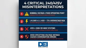
Four errors consistently appear in 240/415V applications — each with real consequences for equipment reliability and protection coordination.
Nominal voltage is not a fixed operating point. Equipment must perform correctly across the full Range A band (±5% to -10% utilization voltage), not only at the 240V or 415V nameplate value. Specifying narrow voltage tolerance windows creates failure risk during routine utility fluctuations.
Line-to-neutral (240V) and line-to-line (415V) are not interchangeable. Connecting 240V-rated single-phase equipment across two phases applies 415V — approximately 73% overvoltage (415/240 = 1.73). This exceeds NEMA MG 1's maximum allowable +10% by more than 7x and immediately surpasses transformer overvoltage limits. Equipment rated for 240V line-to-neutral connects between a phase conductor and neutral only.
240/415V systems don't behave like 208Y/120V or 480Y/277V. These are distinct architectures with different transformer configurations, equipment compatibility requirements, and protection coordination settings. 208Y/120V, 415Y/240V, and 480Y/277V systems are not interchangeable. Operating equipment rated for one system voltage on another requires re-rating or reconfiguration — they aren't interchangeable.
Over-specifying voltage withstand ratings introduces its own risks. Selecting 480V-rated equipment for a 415V system often creates protection coordination mismatches. Circuit breakers, fuses, and protective relays have voltage-dependent operating characteristics. Mixing voltage ratings without recalculating coordination curves risks nuisance tripping or failure to clear faults.
Frequently Asked Questions
What does 240/415 voltage mean?
240/415V designates a three-phase, four-wire Wye system where 240V is the line-to-neutral voltage (measured between any phase conductor and neutral) and 415V is the line-to-line voltage (measured between any two phase conductors). The two values are related by the √3 (1.732) factor inherent to Wye configurations.
Is 415V considered low or high voltage?
415V is classified as Low Voltage under both ANSI C84.1 (systems up to 1000V) and IEC 61140:2016 (0–1000V AC RMS). Despite being much higher than 120V or 208V, it does not enter the medium voltage category (typically >1000V).
Why do data centers use 415V?
415V allows data centers to deliver substantially more power per circuit at the same amperage compared to 208V, delivering roughly twice the capacity per circuit. This reduces power feeds per rack, lowers I²R conductor losses, and improves overall power usage effectiveness (PUE) by 4-5%.
What is 415 volts used for?
415V serves three primary applications: three-phase motor loads in industrial and manufacturing environments, high-density IT power distribution in data centers, and as the standard utility distribution voltage in countries including Australia, Malaysia, Kenya, and several others operating at 50 Hz.
Can you run a 415V motor on 240V?
No. A motor rated for 415V line-to-line cannot be run on 240V line-to-line without significant derating or rewinding. The reduced voltage forces the motor to draw excess current, causing overheating, insulation degradation, and eventual failure.
Is 415V AC or DC?
415V in power distribution contexts refers to AC (alternating current) at either 50 Hz or 60 Hz depending on the country or application. IEC 60038:2009 defines 415V exclusively as an AC voltage designation; standard DC power distribution systems do not use this voltage level.