Introduction
If you're wiring a commercial or light industrial panel, the 120/208V 3-phase wye system is what you're most likely working with. This single panel configuration simultaneously serves 120V single-phase, 208V single-phase, and 208V three-phase loads from one set of busbars — no secondary panels or step-down transformers required.
The concept is straightforward, but wiring errors are common in the field — particularly around neutral handling, breaker selection, phase balance, and grounding. These mistakes don't just fail inspection; they create immediate safety hazards and equipment damage that can cost thousands to fix after the fact.
This guide is built to help you avoid those failures. It covers what the 120/208V wye system delivers, what's required before you touch a wire, step-by-step wiring for all three load types, and the most common mistakes that show up in real installations.
Key Takeaways
- Know your busbar layout: L1, L2, L3 (hot), one neutral busbar, and a ground bar — all required in a 120/208V 3-phase wye panel
- Use a 1-pole breaker + neutral for 120V loads; 2-pole breaker for 208V single-phase loads; 3-pole breaker for 208V three-phase loads
- Neutral wire is required for 120V circuits and some three-phase loads; knowing when to include it prevents wiring errors
- Phase load balancing across L1, L2, and L3 prevents transformer stress and excessive neutral current
- NEC color codes: Black (L1), Red (L2), Blue (L3), White (Neutral), Green or bare (Ground)
Understanding the 120/208V 3-Phase Wye System
What 208Y/120V Actually Means
The designation "208Y/120V" describes a three-phase system where three phase conductors are displaced 120 electrical degrees apart. The system delivers 120V line-to-neutral on each phase and 208V line-to-line between any two phases. This relationship comes from the formula: 120V × √3 ≈ 208V.
This differs from the 240V split-phase systems common in residential applications. In a 208Y/120V wye configuration, a single 4-wire system supports both voltage levels simultaneously — making it far more versatile for mixed commercial and industrial loads.
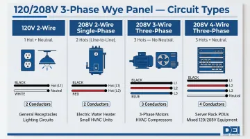
Four Circuit Types Available
120V 2-wire single-phase (hot + neutral):
- Lighting circuits, duplex outlets, office equipment
- Uses one phase conductor and the neutral
- Most common for general-purpose receptacles
208V 2-wire single-phase (two hots):
- Water heaters with 208V-rated elements, baseboard heating
- Single-phase 208V motors
- No neutral required for purely resistive loads
208V 3-wire three-phase (three hots, no neutral):
- HVAC compressors, large pumps, industrial fans
- Most common three-phase motor configuration
- Neutral not needed unless equipment has 120V controls
208V 4-wire three-phase (three hots + neutral):
- Commercial kitchen equipment, data center PDUs
- Equipment requiring both three-phase power and 120V control circuits
- Mixed voltage loads within single equipment
System Derivation
This voltage system is typically derived from delta-wye step-down transformers. A common configuration steps down 480V delta primary to 208Y/120V secondary, providing both phase voltages simultaneously.
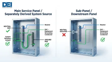
The neutral is derived from the center tap of the wye secondary. Under NEC Article 100, when a transformer creates a new grounded neutral on the secondary side, it becomes a separately derived system — and that classification directly determines whether the neutral bar bonds to or isolates from the panel enclosure. Getting this wrong is a common code violation during panel installation.
What You Need Before Wiring the Panel
Preparation directly impacts both safety and code compliance. Several conditions must be confirmed before any wiring begins.
Equipment and Panel Requirements
Verify the panelboard rating:
- Confirm 120/208V 3-phase 4-wire service rating
- Check main breaker rating matches service ampacity
- Identify three hot busbars, neutral bar, and ground bar locations
In a separately derived system (downstream of a transformer), the neutral bar must be isolated from the enclosure. The ground bar remains bonded to the enclosure. This separation prevents parallel neutral current paths that create safety hazards.
For projects where schedule and code compliance carry real consequences, starting with a pre-assembled, UL 891-certified switchboard — such as those manufactured by DEI Power — reduces field wiring complexity. These units ship with verified busbar configurations, labeled terminals, and integrated grounding infrastructure already in place.
Tools, PPE, and Compliance Readiness
Required tools:
- Torque wrench or screwdriver with torque settings (per NEC 110.14(D))
- True-RMS voltage tester or multimeter
- Wire strippers and conductor labels
- Clamp meter for current measurement
Code compliance verification:
- Confirm NEC Article 408 panelboard requirements are met
- Verify conductor sizing against NEC Table 310.15(B)(16)
- Calculate or obtain available fault current for breaker AIC rating verification
Circuit labeling is a code requirement, not optional housekeeping. NEC 408.4(A) requires every circuit to be legibly identified with a clear, evident, and specific purpose. Place the identification in a circuit directory on or adjacent to the panel door.
Arc flash protection: Before opening any energized enclosure, NFPA 70E-2024 requires Arc Flash PPE Category 1 (minimum 4 cal/cm² arc rating) for panelboards rated 240V and below, assuming maximum 25 kA available fault current and 0.03 second fault clearing time.
How to Wire a 120/208V 3-Phase Panel for Single and 3-Phase Loads
Step 1: De-energize and Verify Incoming Service Conductors
Open and lock out the main disconnect upstream of the panel. Use a properly rated voltage tester to confirm all conductors are de-energized before touching any terminals.
Verify presence of all conductors:
- L1, L2, L3 (three phase conductors)
- Neutral conductor
- Equipment grounding conductor (EGC)
Check incoming conductor sizing against the main breaker rating and NEC ampacity tables. The neutral conductor must be properly sized — in this system, the neutral may carry unbalanced current and cannot be arbitrarily reduced.
Step 2: Terminate Incoming Service Conductors to the Panel
Phase conductor terminations: Connect L1, L2, and L3 to the main breaker line-side terminals (or main lugs in a main-lug-only panel). Maintain color code consistency: Black (L1), Red (L2), Blue (L3). These standard color codes distinguish 208Y/120V systems from higher-voltage 480Y/277V systems (which use Brown, Orange, Yellow).
Critical neutral and ground distinction:
In a standalone main service panel, the neutral bar and ground bar are bonded together. However, in a sub-panel or a panel fed from a separately derived system (transformer secondary), the neutral must float (be isolated from the enclosure), and only the ground bar connects to the enclosure.
Per NEC 250.142, a grounded neutral conductor may be used as the effective ground-fault current path ONLY on the supply side of the service disconnecting means or at the source of a separately derived system.
Downstream bonding is prohibited because it creates parallel neutral current paths through equipment grounding conductors and conduit systems, causing objectionable current on metal enclosures.
Torque requirements: NEC 110.14(D) requires that tightening torque values for terminal connections be as indicated on equipment or in manufacturer installation instructions. An approved means must be used to achieve the indicated torque value. Never over-tighten or under-tighten — both conditions cause connection failures over time.
Step 3: Wire 120V Single-Phase Loads
Install a 1-pole circuit breaker onto any single hot busbar (L1, L2, or L3). Connect:
- Black (or phase-colored) hot wire from breaker output to load's hot terminal
- White neutral wire from neutral bar to load's neutral terminal
- Green or bare EGC from ground bar to load's ground terminal
Applicable loads: 120V duplex outlets, lighting circuits, control circuits, small appliances.
When distributing 120V circuits across the panel, balance the loads across all three phases rather than concentrating them on one phase. This prevents transformer stress and elevated neutral current.
Step 4: Wire 208V Single-Phase Loads
Install a 2-pole circuit breaker spanning any two hot busbars (L1-L2, L2-L3, or L1-L3). Connect:
- Two hot wires (e.g., Black and Red for L1-L2) from breaker terminals to load's two hot terminals
- Green or bare EGC from ground bar to load's ground terminal
Neutral requirement: For purely resistive 208V single-phase loads such as water heaters, neutral is not required. However, equipment with 120V control circuits requires a neutral conductor even though the main load operates at 208V.
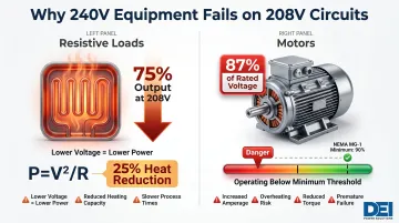
Critical voltage compatibility: 2-pole breakers in a 208V wye panel deliver 208V, not 240V — equipment must be rated accordingly. The voltage difference has real consequences:
- Resistive loads (e.g., heating elements): P = V²/R means a 240V-rated element at 208V produces only 75% of rated output (25% heat reduction)
- Motors: NEMA MG-1 requires operation within ±10% of nameplate voltage; a 240V-rated motor at 208V runs at 87% of rated voltage, falling below the 90% floor and violating NEC 110.3(B)
Step 5: Wire 208V Three-Phase Loads
Install a 3-pole circuit breaker spanning all three hot busbars. Connect:
- Three hot wires (Black/L1, Red/L2, Blue/L3) from breaker to load's three-phase terminals
- Green or bare EGC from ground bar to load's ground terminal
When a neutral is needed: Most three-phase motors run without a neutral. Equipment with 120V control circuits, however, requires a 4-wire, 5-conductor connection: L1, L2, L3, Neutral, Ground.
Common three-phase loads:
- HVAC compressors and packaged units
- Industrial pumps and fans
- Welding equipment
- Server rack power distribution units (PDUs)
Always verify the load's specific wire count requirement from its nameplate or installation manual before making connections.
Key Parameters That Affect Panel Wiring Outcomes
Decisions made before and during wiring — about load distribution, conductor sizing, neutral handling, and grounding — directly determine whether the system operates safely, efficiently, and in compliance with NEC. Getting the physical connections right matters, but these parameters define the outcome.
Phase Load Balance
Single-phase 120V and 208V loads pull current from only one or two phases, creating unequal loading across L1, L2, and L3. In a wye system, this imbalance causes unequal transformer winding stress, elevated neutral current, and potential voltage deviation on lightly loaded phases.
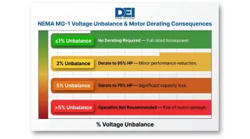
NEMA MG-1 voltage unbalance standards establish performance impact thresholds:
- ≤1% unbalance: No derating required
- 2% unbalance: Derate motor to 95% of rated HP
- 5% unbalance: Derate motor to 76% of rated HP
5% unbalance: Operation not recommended
During circuit layout and breaker assignment, distribute single-phase loads across all three phases as evenly as possible. Calculate phase current imbalance and keep it below 2% for optimal equipment performance. Unbalanced loading can push neutral current to match or exceed phase current, overheating the neutral conductor.
Neutral Conductor Sizing
In a balanced three-phase wye system, neutral current cancels to near zero. In mixed systems with non-linear loads — switching power supplies, VFDs, LED lighting — harmonic currents add rather than cancel on the neutral instead.
Triplen harmonics (3rd, 9th, 15th, 21st order) are zero-sequence harmonics that add cumulatively in the neutral conductor. Neutral current can reach up to 173% of phase current levels, even when all three phases are completely balanced.
For panels serving significant non-linear loads — data centers, commercial offices with dense LED or computer loads — size the neutral conductor at full or double the phase conductor ampacity. NEC 310.15(E) treats the neutral as current-carrying in 4-wire, 3-phase wye circuits where the majority of the load is nonlinear.
Real-world consequence: A Colorado data processing center case study documented 65% total harmonic distortion (THD), neutral-to-ground voltages up to 13 VRMS, and over 4,000 monthly transmission errors. Remediation required 200% rated copper neutral bus and K-13 rated transformers.
Breaker Type and Interrupting Rating
Breakers must be rated for the correct voltage and carry an interrupting rating (AIC) equal to or greater than the available fault current at the panel. Underrated breakers are a common code violation — and a catastrophic failure risk during fault events.
NEC 240.85 permits slash-rated circuit breakers (such as 120/240V) in solidly grounded 208Y/120V systems because the voltage to ground (120V) does not exceed the lower rating and line-to-line voltage (208V) does not exceed the higher rating.
Two steps apply here:
- Calculate or obtain available fault current from utility or upstream transformer data
- Verify every breaker's listed AIC rating meets or exceeds that value
NEC 110.24 requires service equipment in non-dwelling units to be field-marked with the maximum available fault current and the date the calculation was performed.
Grounding and Bonding Configuration
Whether the neutral bar is bonded to or isolated from the enclosure depends entirely on whether this panel is a main service panel or a sub-panel fed from a separately derived system. This single distinction governs fault current return paths and directly affects personnel safety.
In a panel fed from a transformer secondary (separately derived system per NEC Article 250), the system bonding jumper connects the neutral to the enclosure at the transformer — not at the downstream panel. The downstream panel neutral bar must be isolated; only the equipment grounding conductor (EGC) connects the enclosure to ground.
The supply-side bonding jumper is sized per NEC 250.102 (Table 250.102(C)(1)) based on the area of the secondary phase conductor — not per NEC 250.122, which covers load-side equipment grounding conductors based on overcurrent device rating. This distinction is a common area of error in field installations.
Common Mistakes When Wiring a 120/208V 3-Phase Panel
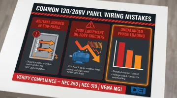
These three wiring errors show up repeatedly in 120/208V 3-phase installations — and each one can cause code violations, equipment damage, or degraded system performance.
Bonding the Neutral to the Enclosure in a Sub-Panel
This creates parallel neutral current paths through equipment grounding conductors and conduit systems, causing objectionable current on metal enclosures per NEC 250.6. The neutral bar must float in any panel that is not the first means of disconnect after the separately derived system bonding point.
Installing 240V-Rated Equipment on 208V Circuits
208V and 240V are not interchangeable voltage classes. Resistive loads such as water heaters will deliver 25% lower heat output, and a 240V motor running at 208V operates at only 87% of rated voltage — below NEMA MG-1's 90% minimum threshold — which violates NEC 110.3(B). Always verify equipment is rated for 208V or dual-rated 208-240V before installation.
Failing to Balance Single-Phase Loads Across Phases
Concentrating 120V circuits on L1 while leaving L2 and L3 lightly loaded causes:
- Transformer imbalance and elevated neutral current
- Voltage sag on the overloaded phase
- Potential overheating of phase conductors over time
Panel scheduling and load balancing must be completed before circuit assignments are finalized, not corrected after the fact.
Troubleshooting Common Issues After Wiring
Most post-wiring issues in 120/208V panels trace back to connection errors, incorrect configuration, or load imbalance. Systematic verification with test equipment cuts diagnosis time significantly — start with the most common failure points below.
Voltage Readings Lower Than Expected on 208V Circuits
Phase-to-phase readings below 208V (e.g., 195–202V) point to one of three root causes:
- Severe load imbalance pulling down one phase
- Loose or high-resistance connection at the busbar or breaker terminal
- Transformer tap set incorrectly for actual load
Use a true-RMS voltmeter to measure L1-L2, L2-L3, and L1-L3 at the panel under load. Compare readings to identify which phase is sagging, then re-torque all busbar and breaker terminations. Review transformer tap settings and load schedule for balance corrections.
Elevated Neutral Current / Overheating Neutral Bar
High neutral current points to two distinct problems: severe phase load imbalance on 120V single-phase circuits, or non-linear loads generating triplen harmonics that add on the neutral instead of canceling.
Diagnose by measuring L1, L2, L3, and neutral current simultaneously under full load with a clamp meter, then:
- Calculate phase imbalance percentage
- If neutral current approaches or exceeds phase current, use a power quality analyzer to check harmonic content
- Consider re-sizing the neutral conductor or adding harmonic filtering if harmonics are confirmed
IEEE 519 sets the distortion limits to reference: 5% THD voltage maximum, with no single harmonic exceeding 3%.
Tripped Breakers With No Apparent Overload
Unexpected trips without visible overload usually come down to three causes: wrong voltage-rated breaker installed, insufficient AIC rating for available fault current, or a ground fault or arcing connection at the load termination.
Work through these checks in order:
- Verify breaker voltage rating and AIC rating against panel specifications
- Perform an insulation resistance test on circuit conductors to detect ground faults
- Inspect load-side terminations for loose connections or arcing signs (discoloration, melted insulation)
- Replace any breaker not listed for use in a 120/208V 3-phase panel
Frequently Asked Questions
How to get 120V from 208V 3-phase?
In a 120/208V wye system, 120V is available between any single hot phase conductor (L1, L2, or L3) and the neutral conductor. This is the phase-to-neutral voltage of the wye configuration and requires a 1-pole breaker connected to one hot busbar plus a neutral wire routed from the neutral bar to the load.
Does a 208 circuit need a neutral?
A 208V single-phase circuit (2-pole breaker, two hot wires) does not require a neutral for purely resistive or motor loads. A neutral is only needed when the equipment includes 120V control circuits or mixed-voltage internal components — the same rule applies to 208V three-phase circuits.
How is 208 3-phase wired?
208V three-phase uses a 3-pole breaker across all three hot busbars (L1, L2, L3). Three hot conductors (Black, Red, Blue per NEC) run to the load terminals along with an equipment grounding conductor, plus a neutral only if the load requires it.
What does 208Y/120V mean?
208Y refers to 208V line-to-line voltage in a Wye (Y) system, where the "Y" indicates secondary windings meet at a shared neutral center point. The "/120" means 120V is also available between any phase conductor and that neutral — both voltages drawn from the same 4-wire panel.
Can 208V run on 120V?
No — and the reverse is equally dangerous. Running 208V-rated motors or heating elements on 120V causes severely reduced output and motor failure. Connecting 120V equipment to a 208V circuit exposes it to nearly double its rated voltage and will damage it immediately.
How does a 3-phase distribution board work?
A 3-phase distribution board receives three hot phase conductors, a neutral, and a ground from the supply source, distributes them across parallel busbars inside the enclosure, and allows 1-pole, 2-pole, and 3-pole breakers to tap off those busbars to feed individual branch circuits. Overcurrent protection protects every circuit, and busbars are sized to carry the full panel load capacity.