Introduction
Misspecify the voltage on a 208Y/120V system and you're looking at wrong equipment, failed inspections, and change orders that blow the project budget. This is the dominant power distribution standard for commercial buildings, data centers, and light industrial facilities across North America — and it's also one of the most frequently misunderstood.
According to ANSI C84.1, 208Y/120V represents a preferred nominal voltage for three-phase four-wire systems—and the designation itself encodes critical system information. The Wye configuration, the √3 voltage relationship between its two output levels, and the four-wire topology are interdependent — together they determine which loads the system supports and how downstream equipment must be specified.
This guide breaks down what the 208Y/120V designation actually means and how the Wye configuration produces both voltages from a single service. It covers which load types each voltage supports and what engineers and facility teams need to know when specifying distribution equipment for commercial and industrial applications.
Key Takeaways
- 208Y/120V provides two simultaneous voltages: 208V phase-to-phase and 120V phase-to-neutral from a single three-phase, four-wire Wye service
- The "Y" denotes a Wye (star) configuration where three phases share a neutral center point, which produces both voltage levels simultaneously
- 120V is derived from 208V ÷ √3 (1.732 ≈ 120V), not from a separate winding
- All breaker types draw from the same panel: single-pole for 120V, two-pole for 208V single-phase, three-pole for 208V three-phase
- 208V and 240V are not interchangeable; equipment rated for one may fail or underperform on the other
What 208Y/120V Means: Decoding the System Designation
The designation 208Y/120V is standardized ANSI/NEC notation that fully describes a three-phase, four-wire electrical system. Each element conveys specific technical information:
- 208 = phase-to-phase voltage (measured between any two phase conductors)
- Y = Wye (star) transformer secondary winding configuration
- /120 = phase-to-neutral voltage (measured between any phase conductor and neutral)
ANSI C84.1, the authoritative standard for electric power system voltage ratings, defines this notation format. Per Table 1, Note (a): "Four-wire systems are designated by the phase-to-phase voltage, followed by the letter Y, a slant line, and the phase-to-neutral voltage." The standard lists 208Y/120 in boldface as a preferred nominal voltage.
The Wye Configuration Explained
The "Y" represents the physical geometry of three transformer secondary windings joined at a common neutral point, forming a star or Y shape:
- The three arms = three phase conductors (L1, L2, L3)
- The center point = grounded neutral conductor
This configuration is distinct from a Delta system, which has no neutral point and cannot simultaneously produce two voltage levels. The Wye is chosen specifically because it enables both 120V single-phase circuits and 208V three-phase circuits from the same service. That dual-voltage capability is also what defines the four-wire structure.
The Four-Wire Designation
A 208Y/120V system consists of:
- Three ungrounded phase conductors (L1, L2, L3)
- One grounded neutral conductor
- One separate equipment ground (required by NEC but counted separately)
NEC 250.20(B)(2) requires three-phase four-wire Wye systems where the neutral serves as a circuit conductor to be grounded. The neutral is brought to the service equipment per NEC 250.24(C) because it serves as the ground-fault return path.
208Y/120V vs. 120/208V: Same System, Different Notation
Both designations refer to the same electrical system. The notation order varies by context:
- 208Y/120V = transformer/service designation (phase-to-phase first)
- 120/208V = equipment nameplate or panel labeling (phase-to-neutral first)
The wiring, voltage levels, and grounding requirements are the same regardless of which notation appears on the drawing or equipment label.
How the Wye Configuration Produces Both 208V and 120V
The relationship between 208V and 120V is governed by √3 (square root of three), approximately 1.732. This is not arbitrary—it's a fundamental phasor relationship resulting from the 120-degree angular displacement between three phases in a balanced Wye system.
The Formula
V(phase-to-phase) = V(phase-to-neutral) × √3
Applying this:
120V × 1.732 ≈ 208V
This relationship holds for all balanced three-phase Wye systems.
Why It's Not Intuitive
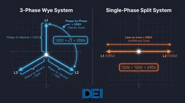
Many engineers expect two 120V phases to add to 240V, as in a residential split-phase system. But in a three-phase Wye, the 120-degree angular offset means voltages do not add arithmetically—they add as vectors, producing 208V instead of 240V.
In a single-phase center-tapped system (typical residential service), two 120V legs are 180 degrees apart and add directly: 120V + 120V = 240V.
In a three-phase Wye, the 120-degree spacing reduces the resultant voltage by the factor of √3—hence 208V, not 240V.
The Role of the Neutral Conductor
The neutral conductor serves two critical functions:
- Establishes the 120V reference for each phase—without it, only 208V phase-to-phase voltages would be accessible
- Carries imbalance current between phases under unequal loading
In a perfectly balanced system, equal current on all three phases causes neutral current to cancel to near-zero. In an unbalanced system—common when single-phase 120V loads dominate—neutral current increases and can cause voltage deviation, affecting sensitive equipment and transformer efficiency.
ANSI C84.1 Voltage Tolerance Ranges
Equipment must operate across a defined tolerance band, not just at nominal values. ANSI C84.1-2016 establishes two voltage ranges for 208V utilization voltage:
| Parameter | Range A | Range B |
|---|---|---|
| Utilization Voltage - Maximum | 218V (+5%) | 220V (+5.8%) |
| Utilization Voltage - Minimum | 187V (−10%) | 180V (−13.3%) |
Range A represents normal operating conditions. Range B represents abnormal conditions requiring corrective action. Equipment must be specified to operate reliably across these ranges—especially motors operating near the lower tolerance limit.
Load Balance and System Performance
Balanced loads produce:
- Minimal neutral current
- Stable phase-to-neutral voltages
- Maximum transformer efficiency
Unbalanced loads produce:
- Increased neutral current (potentially exceeding phase conductor current)
- Voltage deviations at the panel
- Reduced equipment lifespan and efficiency
Facilities with significant single-phase nonlinear loads (computers, LED lighting, VFDs) must size neutral conductors carefully to avoid overheating and voltage distortion.
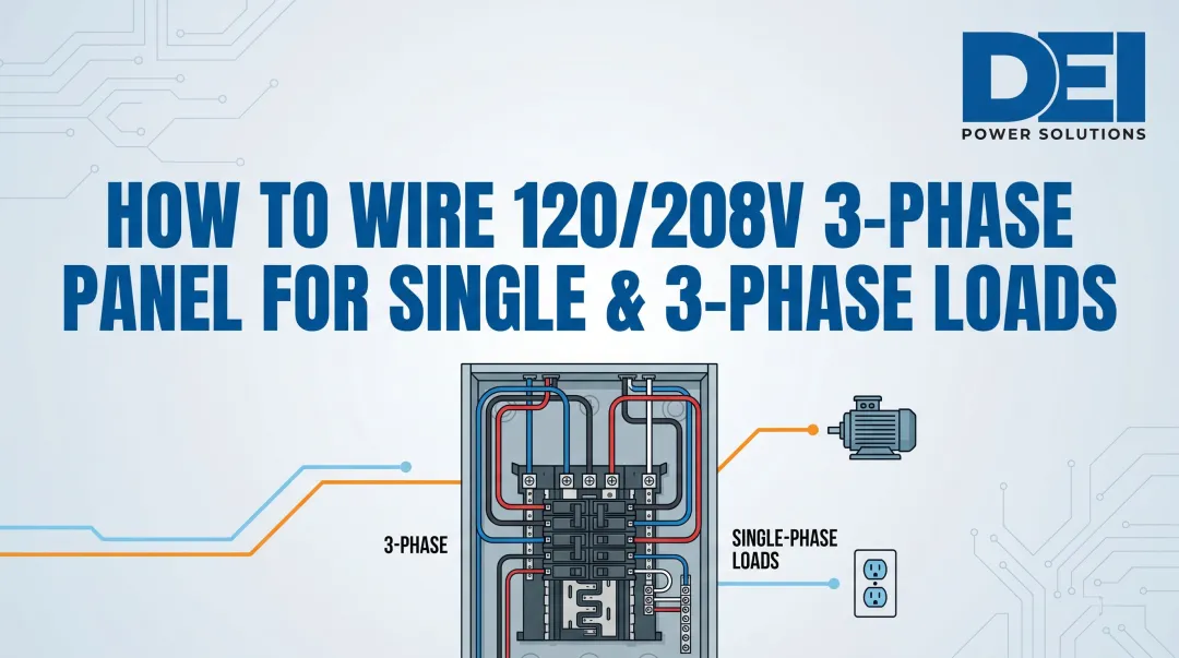
Available Voltages, Circuit Types, and Supported Loads
A single 208Y/120V panel provides three distinct circuit types, each accessed by a specific breaker configuration:
| Voltage | Breaker Type | Conductor Count | Typical Applications |
|---|---|---|---|
| 120V Single-Phase | 1-pole | Phase + Neutral + Ground | Lighting, receptacles, controls, office equipment |
| 208V Single-Phase | 2-pole | Two Phases + Ground | Water heaters, small HVAC units, electric ranges |
| 208V Three-Phase | 3-pole | Three Phases + Ground | Motors, large HVAC, industrial equipment, data center PDUs |
Each circuit type draws from the same panel — what changes is how many phases the breaker connects. This distinction becomes especially important when specifying motor-driven equipment.
Motor De-Rating on 208V Systems
A motor rated for 230V will produce less torque when operated at 208V because motor output varies with the square of voltage.
Per NEMA MG-1 Part 12.44:
- Motors must operate within ±10% of rated voltage
- At 208V, a 230V-rated motor operates at 90% of nameplate voltage (208 ÷ 230 = 0.90)
- Starting and breakdown torque drop to approximately 81% of rated (0.90² = 0.81)
- This represents a 19% torque loss
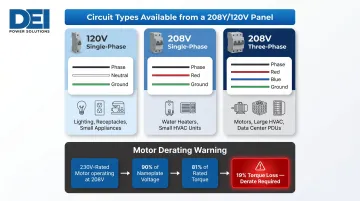
Specify motors rated 208-230V (dual-rated), not 230V-only, for 208Y/120V systems. Dual-rated motors are designed to perform reliably at either voltage — removing the derating risk entirely.
NEC Color Code Conventions
The commonly cited color scheme for 208Y/120V systems follows industry convention — the NEC mandates colors only for neutral and ground conductors, not for phases:
| Conductor | Color | NEC Article | Status |
|---|---|---|---|
| L1 (Phase A) | Black | — | Convention |
| L2 (Phase B) | Red | — | Convention |
| L3 (Phase C) | Blue | — | Convention |
| Neutral | White or Gray | NEC 200.6 | Mandatory |
| Ground | Green or Bare | NEC 250.119 | Mandatory |
NEC 210.5(C) requires phase conductor identification only when a premises has branch circuits from more than one voltage system (for example, both 208Y/120V and 480Y/277V). The chosen color scheme must be posted at each panelboard.
Where 208Y/120V Systems Are Specified and Why
Commercial Buildings and Light Industrial
208Y/120V is the standard utility service for:
- Mid-rise office buildings
- Schools and universities
- Hospitals and healthcare facilities
- Retail and hospitality
- Light manufacturing
This contrasts with:
- Residential service: 120/240V single-phase split (center-tapped transformer)
- Heavy industrial: 480Y/277V three-phase (higher voltage reduces current for large motor loads)
Data Centers and Colocation Facilities
208Y/120V dominates North American data center rack-level PDU distribution. Schneider Electric White Paper 27 documents key advantages:
- 1-2% power supply efficiency improvement when distributing 208V versus 120V to IT equipment
- Higher power density: 208V receptacles support approximately 3,600W (20A) and 5,400W (30A), versus 1,440W for a 120V/15A outlet
- Auto-ranging PSUs: most IT equipment (typically 100-240V input range) runs more efficiently at higher voltages
The U.S. DOE Best Practices Guide for Energy-Efficient Data Center Design (July 2024) recommends: "Maintain a higher voltage for as long as possible to minimize the current," noting that PDUs commonly convert 208V AC to 120V AC via built-in step-down transformers for low-voltage equipment.
Why Confirmation Matters
These efficiency and density advantages only hold when equipment is matched to the correct service voltage. Installing 240V-rated equipment in a 208Y/120V building creates real consequences:
- Operational failures or nuisance tripping
- Reduced output and performance
- Premature equipment failure
The reverse carries the same risk: 208V-rated devices connected to 240V service face insulation damage and failure. Confirming service type before specifying equipment is a non-negotiable step for facility teams and contractors alike.
Common Misinterpretations and Specification Errors
Misconception #1: "208V is close enough to 240V"
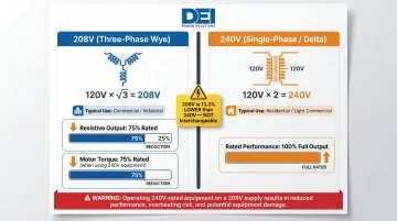
208V and 240V come from fundamentally different system configurations and are not interchangeable.
| Attribute | 208V | 240V |
|---|---|---|
| Source | Three-phase Wye | Single-phase center-tap or Delta |
| Derivation | 120V × √3 = 208V | 120V × 2 = 240V |
| Phase-to-Neutral | 120V | 120V |
| Typical Use | Commercial/industrial three-phase | Residential/light commercial |
208V is 13.3% lower than 240V (208 ÷ 240 = 0.867). This produces significant performance impacts:
- Resistive loads (heaters): Output drops to approximately 75% of rated ((208 ÷ 240)² = 0.75)
- Motors: A 240V-rated motor on 208V draws higher current, overheats, and delivers only 75% of rated torque
- HVAC equipment: Voltage mismatch is a leading cause of compressor failure
Misconception #2: "120V availability means it's a single-phase service"
The 120V in a 208Y/120V system is a phase-to-neutral voltage within a three-phase Wye service — not a single-phase service. Misidentifying it leads to:
- Incorrect transformer sizing
- Wrong panel selection
- Flawed load calculations
Misconception #3: "My meter reads 208V but it should be 240V—the voltage is low"
Technicians measuring 208V phase-to-phase and 120V phase-to-neutral sometimes assume any phase-to-phase reading should be 240V and flag it as deficient. That's a misreading of a correctly operating system.
A 208Y/120V system is designed to deliver 208V. If you measure 208V ± tolerance, the system is functioning as intended — and equipment specified for this voltage will perform accordingly.
Specifying Distribution Equipment for a 208Y/120V System
Equipment Voltage Class and Rating
208Y/120V systems require:
- Switchboards and panelboards rated for 600V class (or 1,000V per revised NEC)
- Circuit breakers rated for 208V AC (not just 120V or 240V)
- Neutral bus sizing to carry potential imbalance current, not just matched to phase conductors
NEC Article 110, Part II governs equipment operating at 1,000V or less. Equipment rated "600V class" is designed, tested, and listed for any system at or below 600V nominal, including 208Y/120V, 240V, and 480Y/277V.
UL 891-Certified Switchboards for 208Y/120V
UL 891 (current edition: 2019) establishes requirements for low-voltage, dead-front switchboards rated at 1,000V AC or less. UL 891-certified switchboards are the appropriate distribution-level product for 208Y/120V commercial and industrial applications.
Key UL 891 specifications:
- Dead-front construction (no exposed live parts)
- Short-circuit withstand ratings from 10,000 to 200,000 amperes
- Only UL-listed or recognized components permitted
- Designed for commercial and light industrial environments
DEI Power manufactures UL 891-certified switchboards in ratings from 400A to 4,000A, built with Siemens components at their Ontario, California facility. Units are available in NEMA 1 (indoor) and NEMA 3R (outdoor) enclosures, with BABA compliance for federally funded projects and lead times of 4–6 weeks for custom builds.
Correct neutral bus sizing is one of the most commonly overlooked specifications when selecting distribution equipment for these systems.
Neutral Bus Sizing for 208Y/120V Systems
NEC 220.61(C) prohibits applying demand factor reductions to the nonlinear load portion in four-wire Wye systems. When serving significant single-phase nonlinear loads (computers, LED lighting, VFDs), triplen harmonics (3rd, 9th, 15th order) sum additively on the neutral conductor, potentially causing neutral current to exceed phase conductor current.
NEC 310.15 requires the neutral to be counted as a current-carrying conductor for ampacity adjustment when harmonic currents are present.
Best practice: Size neutral conductors and bus bars based on calculated imbalance current and, where practical, measurement with a True RMS ammeter—not on the assumption that neutral = phase conductor size.
Circuit Breaker Voltage Ratings
NEC 240.85 governs circuit breaker voltage ratings. For 208Y/120V systems:
- Slash-rated breakers (e.g., 120/240V) are permitted in solidly grounded systems where phase-to-ground voltage does not exceed the lower rating and phase-to-phase voltage does not exceed the higher rating
- A 208Y/120V system (120V to ground, 208V phase-to-phase) satisfies both conditions for 120/240V slash-rated breakers
- The breaker's short-circuit current rating (SCCR) must equal or exceed the available fault current at the point of supply
System Documentation Requirements
Before ordering, confirm these system parameters:
- Service voltage designation (208Y/120V)
- Transformer secondary configuration (Wye with grounded neutral)
- Available fault current (SCCR) at the service point
- Phase configuration (three-phase, four-wire)
- Neutral sizing requirements based on load calculations
DEI Power's engineering team provides specification reviews, application guidance, and detailed electro-mechanical schematics to ensure accurate system design and code compliance before production begins.
Conclusion
208Y/120V is a complete system configuration, not just a voltage rating. The Wye topology, the √3 voltage relationship, the four-wire structure, and the dual-voltage output are interdependent — each one affects how the system behaves and how equipment must be specified.
Misidentifying this system carries real consequences on commercial, industrial, and data center projects:
- Confusing 208V with 240V leaves equipment running below rated voltage
- Misreading Delta vs. Wye causes neutral bonding errors and code violations
- Ignoring the neutral eliminates the 120V single-phase capacity the system depends on
For contractors, engineers, and facility teams specifying switchgear and distribution equipment, getting the system configuration right from the start prevents change orders, inspection failures, and schedule setbacks that rarely fix themselves cheaply.
Frequently Asked Questions
What does 208Y/120V mean and what does the "Y" stand for?
208Y/120V describes a three-phase Wye-configured system: "208" is the phase-to-phase voltage, "120" is the phase-to-neutral voltage, and "Y" denotes the Wye (star) transformer secondary winding configuration. That Wye configuration creates a neutral center point from which the 120V measurement is taken.
How do you get 120V from a 208Y/120V three-phase system?
120V is measured between any single phase conductor and the neutral conductor. This relationship is defined by the Wye geometry: 208V ÷ √3 (1.732) ≈ 120V—not a separate winding, but a result of the 120-degree phase spacing in a Wye configuration.
What voltages are available to loads in a 208Y/120V system?
Three voltages are available: 120V single-phase (1-pole breaker, phase-to-neutral), 208V single-phase (2-pole breaker, phase-to-phase), and 208V three-phase (3-pole breaker, all three phase conductors).
Is 208V the same as 220V or 240V?
No. 208V, 220V, and 240V are distinct system voltages from different configurations. 208V comes from a three-phase Wye service; 240V typically comes from a Delta or residential split-phase service. Equipment rated for one cannot be substituted on another without underperformance or failure risk.
Do they make breakers rated for 208V?
Yes. Circuit breakers are available with 208V AC ratings, and breakers installed in a 208Y/120V panel must carry the correct voltage rating for their application. 120/240V slash-rated breakers are permitted in solidly grounded 208Y/120V systems, provided the interrupt rating is verified against available fault current.
How can you tell whether a service is Delta or Wye?
A Wye service has a neutral conductor, and its phase-to-neutral voltage equals the phase-to-phase voltage divided by √3. A Delta service has no neutral—only three phase conductors plus ground—and measures the same voltage between all conductor pairs. Confirm either configuration using the utility or transformer nameplate documentation.