This guide addresses what low voltage power systems are, how they're configured, and the best practices that separate reliable, code-compliant installations from problem-prone ones. It's written for contractors, engineers, and facility teams working on commercial buildings, industrial plants, data centers, and healthcare facilities where power distribution operates at common U.S. service voltages: 120V, 208V, 240V, 277V, and 480V. This guide does not cover signal-level wiring such as fire alarms, security cameras, or communication systems.
TLDR:
- Low voltage power systems distribute electricity at 1000V nominal or less per NEC Article 100
- System selection (208Y/120V vs. 480Y/277V) directly affects equipment cost, conductor sizing, and total installation expense
- UL 891-certified switchboards and proper fault current studies are mandatory for code compliance and safety
- Undersized equipment and skipped coordination studies are the top causes of inspection failures and costly rework
- NEC 110.26 working clearance violations remain among the most frequent compliance issues in commercial electrical inspections
What Is a Low Voltage Power System?
A low voltage power system is electrical infrastructure that delivers power to end loads at voltages 1000V nominal or less, per NEC Article 100. This threshold separates standard premise wiring from medium- and high-voltage installations, which are governed by NEC Article 490. In U.S. commercial and industrial settings, low voltage systems operate at five standard voltages established by ANSI C84.1-2020: 120V, 208V, 240V, 277V, and 480V.
These systems represent the final stage of the power grid—the last step after utility transmission and medium-voltage distribution. The typical power flow chain works as follows:
- Utility high voltage transmission lines
- Substation step-down transformers
- Medium voltage distribution feeders
- Distribution transformer (steps down to LV)
- Low voltage switchboard or switchgear
- Panelboards and load centers
- Branch circuits and end loads
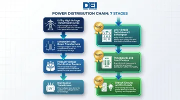
That final stage is where contractors and facility teams operate directly — managing code compliance, load distribution, and system reliability day to day. Design or installation errors here have immediate consequences, from tripped breakers to equipment damage to failed inspections.
Single-Phase vs. Three-Phase Systems
Low voltage systems divide into two broad categories:
Single-phase (240/120V split-phase): A center-tapped transformer delivers both 240V for HVAC and large appliances and 120V for receptacles and lighting. Common in light commercial settings and smaller load applications.
Three-phase systems: Standard for commercial, industrial, and mission-critical environments where load capacity and balanced power delivery matter. Three-phase configurations support higher equipment ratings and allow smaller conductor sizes for equivalent power — making them the practical choice for motor-driven equipment and large facilities.
Types of Low Voltage Power Systems
240/120V Single-Phase Split-Phase
This configuration is standard for residential and small commercial applications. A single-phase, center-tapped transformer delivers 240V across both legs and 120V from each leg to the center-tap neutral. It's appropriate for:
- Residential services
- Small retail spaces
- Offices under 5,000 square feet
- Light-duty equipment loads
Single-phase systems cannot efficiently support large three-phase motors, industrial machinery, or high-density data center loads. For projects requiring more than 200A of total service capacity or significant motor loads, three-phase systems are more practical and cost-effective.
208Y/120V Three-Phase Wye
The most common configuration for commercial buildings, including offices, retail spaces, apartments, schools, and smaller data centers. The wye (star) connection provides:
- 208V line-to-line for three-phase equipment (HVAC units, larger motors, kitchen equipment)
- 120V line-to-neutral for single-phase loads (receptacles, lighting, office equipment)
- A neutral conductor that enables balanced loading across all three phases
This makes it well-suited for mixed-use environments where single-phase convenience loads and three-phase equipment coexist. According to Larson Electronics, the 208V line-to-line voltage equals 120V × √3, maintaining phase separation of 120 electrical degrees.
480Y/277V Three-Phase Wye
The standard for large commercial and industrial facilities, including manufacturing plants, hospitals, large data centers, and utility infrastructure. Per ANSI C84.1-2020, this system delivers:
- 480V line-to-line for motors, HVAC chillers, elevators, compressors, and industrial machinery
- 277V line-to-neutral for LED and fluorescent lighting (delivers 2.3× the wattage capacity of 120V circuits on identical wire and breaker sizes)
Most large facilities use **480V as the primary distribution voltage** and install step-down transformers (480V to 208Y/120V) within the building to serve general-purpose receptacle loads. This two-tier approach optimizes conductor sizing and reduces voltage drop over long feeder runs.
One specification worth confirming during equipment selection: NEMA MG1 Part 10.30 sets 460V as the standard utilization voltage for motors on 480Y/277V systems, with ±10% tolerance.
Three-Phase Delta Systems
Delta-connected systems are less common in new construction but frequently encountered in retrofit and upgrade projects on older industrial and commercial buildings.
240V Ungrounded Delta:
- Three-phase, three-wire system
- Common in older industrial facilities
- Provides 240V phase-to-phase only
- No neutral conductor
Where a neutral conductor is required, the high-leg delta variant is used instead.
High-Leg Delta (Wild Leg): A three-phase, four-wire system with the neutral connected to the center tap of one transformer winding. Provides:
- 240V phase-to-phase across all three phases
- 120V to ground on two phases (A and C)
- 208V to ground on the B phase (the "high leg," "wild leg," or "stinger leg")
Per NEC requirements for high-leg delta systems:
- NEC 408.3(E): The high leg must be assigned to the B phase
- NEC 110.15 and 230.56: The high leg must be identified with a durable, permanent orange outer finish
- NEC 408.3(F)(1): Enclosures must be field-marked: "Caution ___ phase has ___ volts to ground"
- Equipment marked 208Y/120V is not suitable for high-leg delta installations
Matching System Type to Application
Decision Framework:
| Application Type | Recommended System | Reason |
|---|---|---|
| Light commercial, mixed-use, offices <50,000 sq ft | 208Y/120V | Supports both 120V convenience loads and 208V equipment without transformers |
| Heavy industrial, manufacturing, large facilities >50,000 sq ft | 480Y/277V | Reduces conductor costs, supports large motor loads, efficient for long feeder runs |
| Residential, small retail <5,000 sq ft | 240/120V single-phase | Adequate for lighting, receptacles, and residential appliances |
| Retrofit/upgrade on pre-1990 buildings | Verify existing system | May encounter delta configurations requiring special marking and equipment selection |
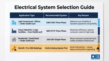
System selection locks in equipment ratings, conductor sizing, and transformer requirements from the start. Confirming the correct voltage class before procurement — not after — is one of the simplest ways to avoid change orders and keep a project on schedule.
Key Components of a Low Voltage Power System
Distribution Transformers
The distribution transformer steps utility or medium-voltage power down to the usable low voltage service level. Selection factors include:
kVA Rating:
- Size to total connected load plus demand factors per NEC Article 220
- Add capacity buffer for future growth (typically 20-25%)
- Undersized transformers cause voltage drop, overheating, and premature failure
Voltage Configuration:
- Primary voltage matches utility supply (common: 12.47kV, 4.16kV, or 480V)
- Secondary voltage matches building distribution system (120/208V, 277/480V, etc.)
Single-Phase vs. Three-Phase:
- Match to load requirements and system architecture
- Three-phase required for balanced industrial and commercial loads
Dry-Type vs. Liquid-Filled:
| Type | Cooling Method | Typical Use | Key Requirement |
|---|---|---|---|
| Dry-type | Air cooling + solid insulation | Indoor commercial/industrial | Periodic cleaning and torque checks |
| Liquid-filled (oil) | Dielectric liquid | Outdoor pad-mount, higher kVA | NEC 450.23/450.27 vault requirements (NEC 450.41–450.48) for indoor use |
Switchboards and Switchgear
The main switchboard or switchgear assembly is the central distribution hub of the low voltage system. It receives power from the transformer secondary and distributes it to downstream panelboards, motor control centers, and large branch circuits.
Key components inside a switchboard:
- Main disconnect breakers
- Bus bars (copper or aluminum)
- Metering sections
- Feeder protective devices (circuit breakers or fuses)
- Instrumentation and monitoring equipment
Code compliance requirement: UL 891 listing is mandatory for switchboards rated at 1000V or less with short-circuit currents below 200,000 amperes. UL 891 is the most common North American standard for dead-front switchboards and operates in parallel with NEC requirements.
DEI Power manufactures UL 891-certified switchboards from 400A to 4000A, custom-built to project voltage, layout, and load specifications. Their in-house engineering team reviews one-line diagrams before manufacturing, which helps catch configuration issues early and reduces inspection failures in the field.
Panelboards and Load Centers
Panelboards represent the next distribution stage: they receive power from the switchboard and distribute it to individual branch circuits serving lighting, receptacles, and equipment.
Two main types:
| Type | Description | Application |
|---|---|---|
| Main Lug Panelboard | No main breaker; relies on upstream switchboard for main overcurrent protection | Most common in multi-panel installations |
| Main Breaker Panel | Integral main disconnect and overcurrent protection | Standalone installations, small services |
Per NEC Article 408, panelboards are designed for cabinet or cutout box placement in or against a wall, with front-only access. They're governed by UL 67 standards.
Overcurrent Protection Devices
Molded case circuit breakers (MCCBs) and fuses form the protective backbone of the low voltage system. Two ratings must align at every point of installation.
1. Interrupting Capacity (kAIC Rating):
- Must be at least equal to the available fault current at the point of installation
- Per NEC 110.9, equipment intended to interrupt current at fault levels shall have an interrupting rating sufficient for the available current
- Underrated breakers can fail catastrophically, rupturing during a fault and causing fire, arc flash, and equipment destruction
2. Ampere Rating:
- Sized to conductor ampacity and load requirements
- Must coordinate with upstream and downstream devices
Mismatched ratings are among the most common code compliance failures on commercial projects. Available fault current is determined by utility source strength, transformer kVA and impedance (%Z), and conductor sizes/lengths. An accurate short-circuit study is required to calculate this correctly.
Best Practices for Designing and Installing Low Voltage Power Systems
Perform Thorough Load Calculations Before Specifying Equipment
Calculate total connected load and apply demand factors per NEC Article 220 before selecting any distribution equipment. The 2020/2023 NEC significantly reduced lighting load values to reflect LED adoption:
| Occupancy Type | 2020/2023 NEC (VA/ft²) | Prior NEC (VA/ft²) |
|---|---|---|
| Offices | 1.3 | 3.5 |
| Hospitals | 1.6 | 2.0 |
| Warehouses (storage) | 0.1 | 0.25 |
| Retail Stores | 1.9 | — |
Critical steps:
- Verify which NEC edition the Authority Having Jurisdiction (AHJ) enforces
- Add capacity buffer of 20-25% to accommodate future load growth
- Consider NEC 220.42 demand factors for specific occupancies
Consequence of undersizing: Specifying a switchboard at 100% of today's calculated load leaves no room for added circuits, new equipment, or tenant changes. Replacing a switchboard mid-project or post-occupancy costs 3-5× more than properly sizing it during design.
Design for Proper Overcurrent Protection Coordination
Conduct or require a protective device coordination study per IEEE 242-2001 (IEEE Buff Book) to ensure that in the event of a fault, only the device nearest the fault opens, preventing a branch-circuit fault from tripping the main and blacking out the entire facility.
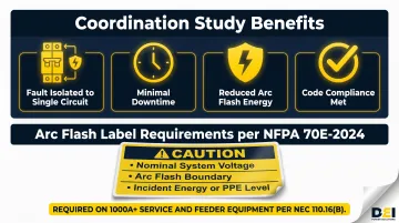
Coordination study benefits:
- Limits outage extent to the faulted circuit only
- Minimizes downtime and operational disruption
- Reduces arc flash incident energy at upstream equipment
- Satisfies code-compliance requirements for selective coordination in critical systems
Arc flash hazard analysis: Per NFPA 70E-2024, equipment must be labeled with nominal system voltage, arc-flash boundary, and at least one of: available incident energy, minimum arc rating of clothing, or PPE level. NEC 110.16(B) requires arc flash labels specifically on service and feeder equipment rated 1000A or more.
Specify Only UL-Listed, Code-Compliant Equipment
NEC 110.3(B) requires that listed and labeled equipment be installed and used in accordance with any instructions included in the listing or labeling. Use of "shall" makes this mandatory—deviation from manufacturer instructions is a direct code violation.
Procurement best practices:
- Verify UL 891 listing for switchboards
- Confirm equipment voltage and amperage ratings match project specifications
- Request one-line diagrams and configuration documentation before delivery
- Work with suppliers who provide in-house engineering support and clear documentation
That last point matters more than it sounds. DEI Power provides specification review before shipment and in-house engineering support from the quoting stage, which catches configuration mismatches before they become field problems.
Ensure Correct Grounding and Bonding Throughout the System
Grounding errors are among the most common causes of nuisance tripping, measurement anomalies, and failed inspections. The equipment grounding conductor (EGC) is a safety ground — non-current-carrying, connecting metal enclosures to ground to provide a fault current return path. The neutral conductor is different: it's a grounded conductor (white or gray insulation) that carries unbalanced current during normal operation.
Where these two connect matters. The NEC is specific:
Neutral-to-Ground Bonding Rules:
- NEC 250.24: Requires bonding at the service equipment via a main bonding jumper
- NEC 250.142: Prohibits neutral-to-ground bonds at downstream panelboards (load side of service disconnect)
- Exception: Separately derived systems (transformers) require their own neutral-to-ground bond at the transformer
Common wiring error: Improper neutral-ground bonding at downstream panelboards causes measurement anomalies, nuisance tripping, and direct code violations. This error appears frequently in commercial electrical inspections.
Plan for Accessibility, Clearance, and Labeling Requirements
NEC Article 110.26 mandates specific working clearances in front of switchboards and panelboards. Violations are among the most frequently cited issues in commercial inspections.
NEC Table 110.26(A)(1) — Minimum Depth of Working Space:
| Voltage to Ground | Condition 1 | Condition 2 | Condition 3 |
|---|---|---|---|
| 0-150V | 3 ft | 3 ft | 3 ft |
| 151-600V | 3 ft | 3.5 ft | 4 ft |
Additional clearance requirements:
- Width: Minimum 30 inches or equipment width, whichever is greater
- Height: Minimum 6 ft 6 in or equipment height, whichever is greater
- Dedicated space: Floor to 6 ft above equipment must be free of foreign systems (pipes, ducts, storage)
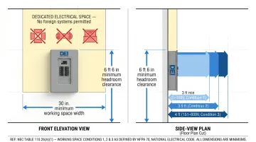
Equipment rated 1200A or more and over 6 ft wide requires entrance at each end, unless working space depth is doubled.
Labeling requirements:
- NEC 408.4(A): Every circuit must be legibly identified for its specific purpose
- NEC 110.16(A): Arc flash warning labels required on switchboards, switchgear, panelboards, and motor control centers
- NEC 110.21(B): Field-applied markings must be durable; handwritten markings prohibited
Poor access planning and missing labels cause project delays, re-inspection fees, and safety risks.
Common Mistakes to Avoid in Low Voltage Power Systems
Undersizing Equipment and Ignoring Future Expansion
Specifying a switchboard at 100% of today's calculated load leaves zero capacity for:
- Added circuits during tenant improvements
- New equipment installations
- Load increases from operational changes
- Compliance with NEC 220 demand factor adjustments
Cost implications:
- Replacing a switchboard mid-project: 3-5× the original equipment cost plus schedule delays
- Post-occupancy replacement: Adds downtime, lost productivity, and emergency service premiums
- Field modifications to add capacity: Often impossible without full replacement
Prevention: Add 20-25% capacity buffer during design stage. Budget a small upfront increase rather than a massive mid-project change order.
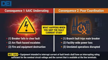
Skipping Fault Current and Coordination Studies
Not knowing the available fault current at each distribution point creates two dangerous outcomes:
1. Insufficient Interrupting Ratings (kAIC Underrating):
- Breaker may fail to clear the fault
- Arc flash hazards escalate
- Physical destruction, fire, and equipment failure result
- Direct violation of NEC 110.9
2. Poor Coordination:
- A single branch circuit fault trips the main breaker
- Entire facility loses power instead of isolating the faulted circuit
- Downtime affects unrelated areas and operations
Arc flash incidents and facility-wide outages are the two most avoidable consequences in power distribution design. IEEE 242-2001 coordination studies and short-circuit calculations are the engineering foundation for preventing both — skipping them is where liability begins.
Using Non-Compliant or Improperly Configured Equipment
Substituting unlisted components or ordering pre-built assemblies that don't match the project's one-line diagram creates:
- Inspection failures and stop-work orders
- Field rework and schedule delays
- Potential liability for code violations
- Increased total project cost
Common scenarios:
- Using 208Y/120V-rated equipment on high-leg delta systems (incompatible)
- Ordering switchboards without verifying kAIC ratings match available fault current
- Accepting equipment without UL 891 certification
- Failing to confirm voltage, amperage, and enclosure type match specifications
Prevention: Work with manufacturers who review your one-line diagram and project specifications before production begins — not after. DEI Power's engineering team does exactly this, verifying configuration accuracy and code compliance at the quoting stage to catch mismatches before they become change orders.
Frequently Asked Questions
What is a low voltage power system?
A low voltage power system is electrical infrastructure that distributes power at voltages of 1000V nominal or less (per NEC Article 100 and ANSI C84.1). Common voltages in U.S. commercial and industrial buildings are 120V, 208V, 240V, 277V, and 480V. These systems deliver power from the utility transformer through switchboards and panelboards to end loads.
What are the types of low voltage power systems?
The three main types are:
- Single-phase split-phase (120/240V) — residential and small commercial applications
- Three-phase wye systems — 208Y/120V for light commercial; 480Y/277V for industrial and large facilities
- Three-phase delta systems — common in older industrial installations
System selection depends on load size, application type, and equipment requirements.
What is a low voltage distribution panel?
A low voltage distribution panel (panelboard or switchboard) is the enclosure that receives power from the step-down transformer and distributes it to branch circuits and sub-panels. It contains bus bars, overcurrent protection devices (circuit breakers or fuses), and in switchboards, the main service disconnect. Switchboards require UL 891 certification for code compliance.
Do electricians install low voltage power systems?
Yes. Licensed journeyman or master electricians install low voltage power distribution components — transformers, switchboards, panelboards, feeders, and branch circuits. All work must comply with NEC requirements and local electrical codes.
Are low voltage power systems expensive to install?
Cost varies widely based on system voltage, amperage, facility type, and equipment specification — a 208Y/120V panelboard project differs significantly from a 480V industrial switchgear installation. According to RSMeans Cost Data and the NECA Manual of Labor Units, labor market rates and required engineering studies are consistent cost drivers. Accurate upfront design and equipment specification reduce change orders and rework.
For custom switchboard configurations built to your project's voltage, layout, and load requirements, contact DEI Power at (866) 773-8050 or sales@deipower.com.