Introduction
Most people understand the utility meter as the point where power enters a building, but that's just the handoff. The critical engineering decisions happen immediately downstream: after the meter, after the main disconnect, and throughout the distribution system that actually runs the facility. While the service entrance marks the regulatory boundary between utility and owner, everything that follows determines whether power reaches your loads safely, reliably, and in compliance with code.
This guide covers the equipment, concepts, and NEC requirements that govern power distribution from the service entrance onward. It's written for contractors, engineers, and facility teams who need clarity on how power flows through a switchboard, what equipment sits downstream, and which code sections apply at each stage.
You'll find detailed explanations of distribution hierarchy, overcurrent protection, transformer secondary rules, and bonding requirements that affect every project from data centers to industrial plants.
TLDR
- The service entrance is where utility power transitions to owner-controlled equipment—typically including conductors, main disconnect, and metering
- Power flows in a clear hierarchy: service entrance → main switchboard → distribution sections → panelboards → branch circuits → loads
- Distribution equipment requires specific UL listings: UL 891 for switchboards, UL 67 for panelboards
- Transformers create separately derived systems subject to NEC 250.30 bonding rules (one neutral-to-ground bond only)
- Transformer secondary conductors must meet NEC overcurrent protection thresholds, including the 10-foot and 25-foot tap rules
What Is the Service Entrance?
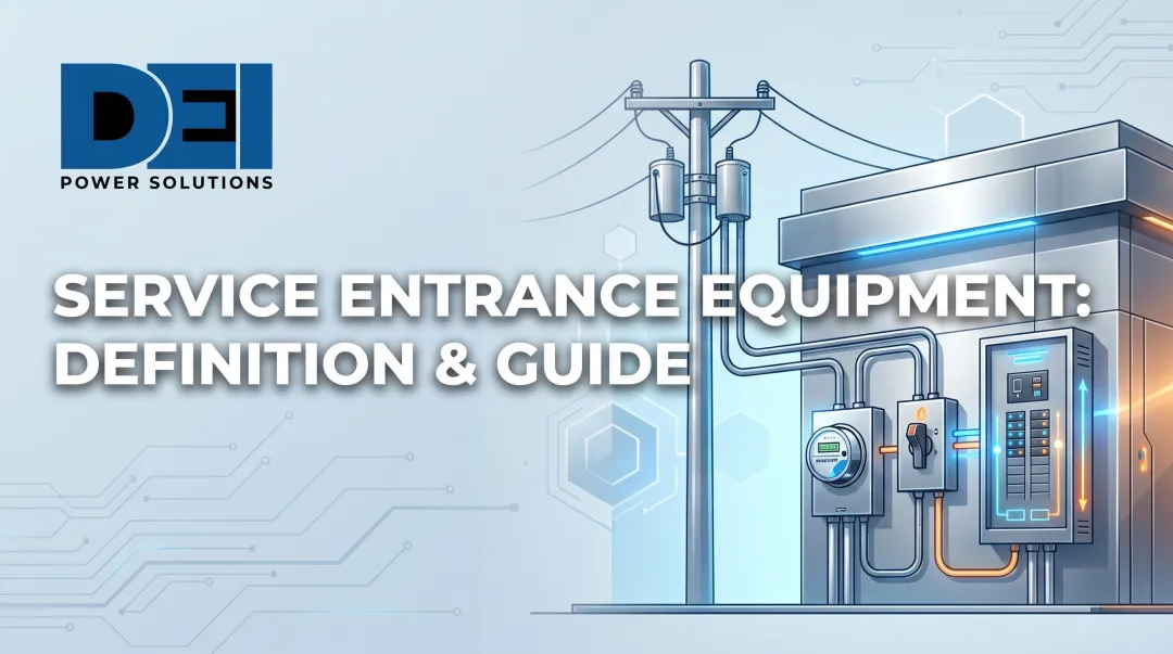
The service entrance is the physical and regulatory boundary where utility conductors meet the owner's electrical system. Per NEC Article 100, service equipment consists of "the necessary equipment, usually consisting of circuit breakers or switches and fuses and their accessories, connected to the load end of service conductors...intended to constitute the main control and cutoff of the electrical supply." This includes service conductors (overhead or underground), the main disconnecting means (circuit breaker or fusible switch), and the utility metering compartment.
Service entrance equipment typically includes:
- Service conductors installed from the utility connection point to the first disconnect
- Main disconnecting means—usually a molded case or insulated case circuit breaker rated for the facility load
- Utility metering compartment designed to ANSI C12.1 and ANSI C12.7 standards
- Overcurrent protection at the point of entry
Utility companies maintain specific requirements for service entrance equipment, and not all switchboards or panels are rated for this application. Equipment listed as "Suitable for Use as Service Equipment" under UL 67 (panelboards) or UL 891 (switchboards) must meet additional bonding and overcurrent requirements beyond standard distribution equipment.
Service Entrance vs. Distribution Equipment
A service entrance-rated device serves as the first point of disconnect from the utility and must include provisions for utility metering and bonding. Distribution equipment receives power from the service entrance and routes it to downstream loads. It is not rated or listed for direct utility connection.
How Power Flows Downstream from the Service Entrance
Power distribution follows a linear path from utility to load. Understanding this hierarchy is essential for proper system design and code compliance.
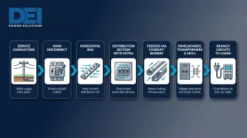
The standard distribution path:
- Service conductors bring utility power to the facility
- Main disconnect in the service entrance switchboard controls all downstream power
- Horizontal bus within the switchboard distributes power across sections
- Distribution section contains individual overcurrent protective devices (circuit breakers or fused switches) for each feeder
- Feeders exit via conduit or busway to downstream equipment
- Panelboards, transformers, or motor control centers receive feeder power
- Branch circuits deliver power to final loads
The main switchboard section houses the main breaker or lugs, utility metering equipment, and sometimes surge protection — it controls all power before it reaches any downstream loads. From there, power transfers to the distribution section via a cross bus or internal bus connection.
Each downstream circuit receives its own disconnect and overcurrent protection before leaving the switchboard enclosure.
Downstream loads are served through:
- Conduit and cable runs to panelboards and equipment
- Busway (busduct) for high-current distribution per NEC Article 368
- Direct feeds to transformers, motor control centers, or large equipment
Once feeders leave the switchboard, they often enter a multi-tier distribution system. A service entrance switchboard feeds secondary distribution switchboards, which feed panelboards, which finally serve branch circuits. This tiered layout supports load management, keeps individual circuit runs shorter, and makes future system expansion more practical.
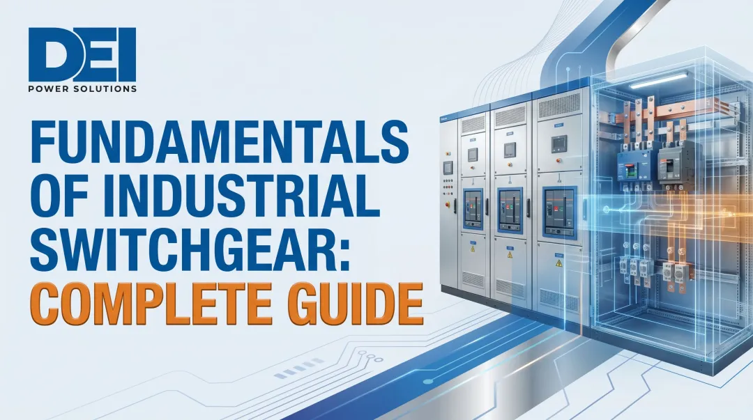
The Distribution Switchboard: The First Major Stop Downstream
Switchboard vs. Panelboard: Key Differences
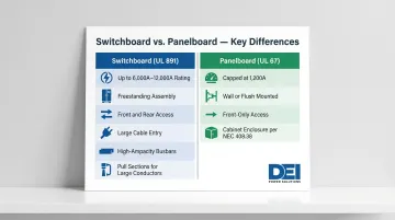
Switchboards and panelboards serve different roles based on ampacity, construction, and accessibility. UL 891 governs switchboards; UL 67 governs panelboards.
Rating and capacity differences:
- Switchboards (UL 891): rated up to 6,000A standard, with some manufacturers offering 12,000A — suited for main distribution with high-density circuit requirements
- Panelboards (UL 67): capped at 1,200A incoming, designed for branch circuit distribution in smaller zones
Physical structure differences:
- Switchboards: freestanding assemblies with front and rear access, built for large cable entry and high-ampacity busbars — often including pull sections for large conductor terminations
- Panelboards: wall-mounted or flush-mounted enclosures with front-only access, installed in cabinets per NEC Article 408.38
Switchboards are the equipment of choice at the first distribution point downstream from the service entrance, especially when incoming loads exceed 1,200A or when the facility requires multiple high-capacity feeders. That capacity requirement flows directly from the internal construction — particularly the busbar system.
Busbars and Overcurrent Protection
The busbar system is the backbone of any switchboard. Horizontal bus distributes power across sections; vertical bus feeds devices within each section. Busbars are copper or aluminum, and their cross-sectional area determines maximum current capacity:
- Copper bus: rated at 1,000A per square inch
- Aluminum bus: rated at 750A per square inch
Overcurrent protective devices in distribution sections:
| Device Type | Standard | Key Characteristics |
|---|---|---|
| Molded Case Circuit Breaker (MCCB) | UL 489 | Thermomagnetic or electronic trip, ratings to 2,500A |
| Insulated Case Circuit Breaker (ICCB) | UL 489 | MCCB with stored-energy mechanism, higher interrupting capacity |
| Low-Voltage Power Circuit Breaker (LVPCB) | UL 1066 | Draw-out design, ratings to 6,000A, highest interrupting ratings |
| Fusible Disconnect Switch | UL 98 | Manual switch with fuse protection, ratings to 6,000A |
Each feeder or branch circuit tapped from the bus must have its own OCPD sized to protect the conductor and load per NEC Article 240. The OCPD rating cannot exceed the conductor ampacity unless the "next size up" rule applies; note that this rule does not apply to transformer secondary conductors.
When sourcing distribution switchboards, UL 891 listing is non-negotiable for code compliance. DEI Power builds UL 891-certified switchboards to custom voltage, ampacity, and layout specifications — with in-house manufacturing that keeps lead times short for time-sensitive projects.
Downstream Equipment: What Comes After the Main Switchboard
Panelboards
Panelboards are the most common downstream equipment. They receive a feeder from the switchboard and divide it into branch circuits for lighting, receptacles, HVAC, and equipment loads.
Panelboard categories (legacy terminology still in common use):
- Lighting/appliance panelboards: Typically up to 600A incoming, serve branch circuits rated 30A or less with neutral connections (lighting, receptacles)
- Power panelboards: 400A–1,200A incoming, serve larger loads like motors, HVAC equipment, and machinery
- Load centers: Residential-grade panels up to 225A, limited application in commercial settings
While the 2008 NEC removed the formal regulatory distinction between these types, the terms remain useful for system planning. All panelboards are subject to the 80% continuous loading rule unless marked for 100% rated operation.
Transformers
Transformers step voltage down to serve loads requiring different voltage than the main distribution system delivers. The most common configuration in commercial facilities is 480V three-phase distribution stepped down to 208Y/120V for receptacle and lighting loads.
Separately derived systems and bonding:
When a transformer has no direct electrical connection between primary and secondary windings (voltage is transferred by induction), it creates a separately derived system.
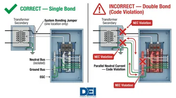
Per NEC 250.30(A)(1), a system bonding jumper must be installed at a single point on the separately derived system—either at the transformer or at the first disconnecting means, but not both.
Double bonding is a code violation. Bonding the neutral to ground at both the transformer and the downstream panel creates parallel neutral paths. This causes:
- Neutral current to flow through equipment grounding conductors during normal operation
- Energized enclosures that present shock hazards
- Interference with overcurrent device coordination
- Stray currents affecting sensitive equipment
Install the system bonding jumper at the transformer enclosure and run a supply-side bonding jumper with the feeder conductors to the first disconnect. Alternatively, place the bonding jumper at the first disconnect and run an unspliced equipment grounding conductor back to the transformer.
Safety Switches and Disconnects
Safety switches provide local disconnection for motors and mechanical equipment downstream. Both fused and non-fused versions satisfy the NEC requirement for a disconnect within sight of equipment being de-energized for maintenance.
Key specifications:
- Ampere ratings: 30A to 1,200A
- Voltage classes: 240V and 600V
- Motor applications: Installed per NEC Article 430
- HVAC applications: Installed per NEC Article 440
NEC Code Requirements Downstream from the Service Entrance
Six-Disconnect Rule (NEC 230.71):
The 2023 NEC permits two to six service disconnects per service, but only in specific configurations:
- Separate enclosures with one main disconnect per enclosure
- Switchboard vertical sections with barriers between each section
- Separate compartments in switchgear or metering centers
- One disconnect per motor control center unit
The 2020 NEC eliminated the allowance for six disconnects in a single enclosure because energized busbars and terminals remain live even when all disconnects are open. Check which NEC edition your jurisdiction has adopted—this affects service entrance equipment configuration on both new and retrofit projects.
Transformer Secondary Conductor Protection (NEC 240.21(C)):
Transformer secondary conductors may be installed without overcurrent protection at the secondary under strict conditions. The most commonly applied rules are:
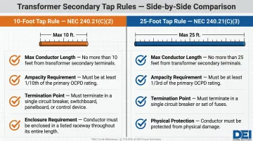
10-Foot Tap Rule [NEC 240.21(C)(2)]:
- Secondary conductors up to 10 feet long
- Ampacity at least 1/10th the primary OCPD rating (adjusted by voltage ratio)
- Conductors must terminate in a switchboard, panelboard, or control device
- Must be enclosed in raceway
25-Foot Tap Rule [NEC 240.21(C)(3)]:
- Secondary conductors up to 25 feet long
- Ampacity at least 1/3rd the primary OCPD rating (adjusted by voltage ratio)
- Conductors terminate in a single circuit breaker or set of fuses
- Must be protected from physical damage
These thresholds are precise and non-negotiable. The "next size up" rule per NEC 240.4(B) does not apply to transformer secondary conductors. If your secondary conductors exceed these length or ampacity limits, you must install overcurrent protection at or near the transformer secondary terminals.
Bonding Requirements After Transformers (NEC 250.30):
NEC 250.30 governs separately derived systems. The system bonding jumper connects the neutral to the equipment grounding conductor at a single point. Installing a second bond at a downstream panel (without meeting Exception 2 conditions) violates code and creates dangerous parallel neutral paths.
Field inspectors frequently cite this violation. Verify bonding is present at only one location:
- Bonded at the transformer: The downstream panel must have isolated neutral and ground buses
- Bonded at the first disconnect: The transformer neutral must remain unbonded
Frequently Asked Questions
What is service entrance equipment?
Service entrance equipment includes the conductors, main disconnect, and metering that connect the utility supply to the owner's electrical system — marking the point where utility power transitions to owner-controlled distribution.
What is the difference between service entrance equipment and distribution system equipment?
Service entrance equipment is the utility-to-owner handoff point, rated and listed specifically for that use. Distribution equipment — switchboards, panelboards, transformers — divides and routes power to loads after that handoff. None of it is rated or approved for direct utility connection.
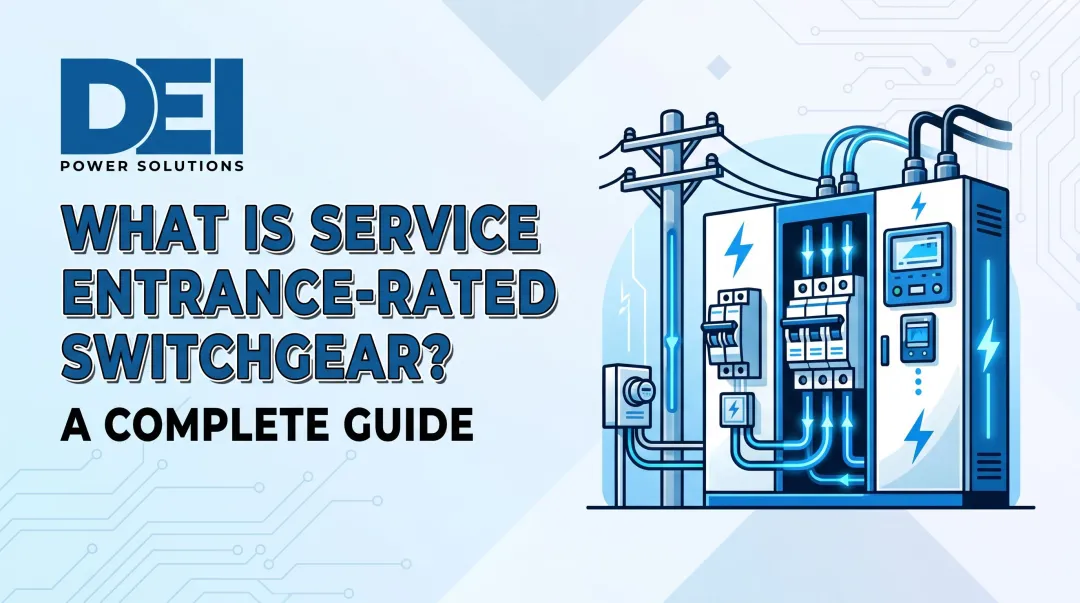
What is a service entrance rated switchboard?
A service entrance rated switchboard is listed and approved as the first point of disconnect from the utility. Beyond standard distribution requirements, it must include utility-specific metering provisions and carry a UL listing marked "Suitable for Use as Service Equipment."
What is the difference between MSB and a distribution board?
A main switchboard (MSB) is the primary distribution point fed directly from the service entrance or transformer. A distribution board (panelboard or sub-switchboard) is downstream equipment that receives a feeder from the MSB and divides power into smaller circuits.
Does the first panel after a transformer need to be bonded?
Yes, per NEC 250.30, the neutral-to-ground bond (system bonding jumper) for a separately derived system must be made at the first disconnecting means downstream of the transformer—or at the transformer itself, but only one location, never both.
Do I need a main breaker after a transformer?
NEC requires overcurrent protection for transformer secondary conductors, but whether a dedicated main breaker is needed at the panel depends on conductor length, ampacity, and transformer impedance. See NEC 240.21(C) for the 10-foot and 25-foot tap rule thresholds that govern most installations.