Testing isn't a one-time commissioning formality. It's a structured, ongoing discipline that protects personnel, ensures NEC and NFPA compliance, and prevents costly unplanned downtime. Arc flash incidents alone result in an estimated 5 to 10 events daily in U.S. electrical equipment, causing approximately 7,000 burns, 2,000 hospitalizations, and 400 deaths annually, according to NFPA research. Every test you perform is a frontline defense against these statistics.
Key Takeaways
- Low voltage switchgear testing verifies insulation integrity, connection quality, protective device operation, and system safety before energization and during routine maintenance
- Core test types — insulation resistance (megger), dielectric withstand (hi-pot), and contact resistance (DLRO) — are governed by IEC 61439, ANSI/NETA, and NFPA 70E
- Follow a structured sequence: pre-test safety → visual/mechanical inspection → electrical tests → documentation and QC sign-off
- Most field failures trace back to skipped or shortcut phases — especially insulation verification and interlock checks
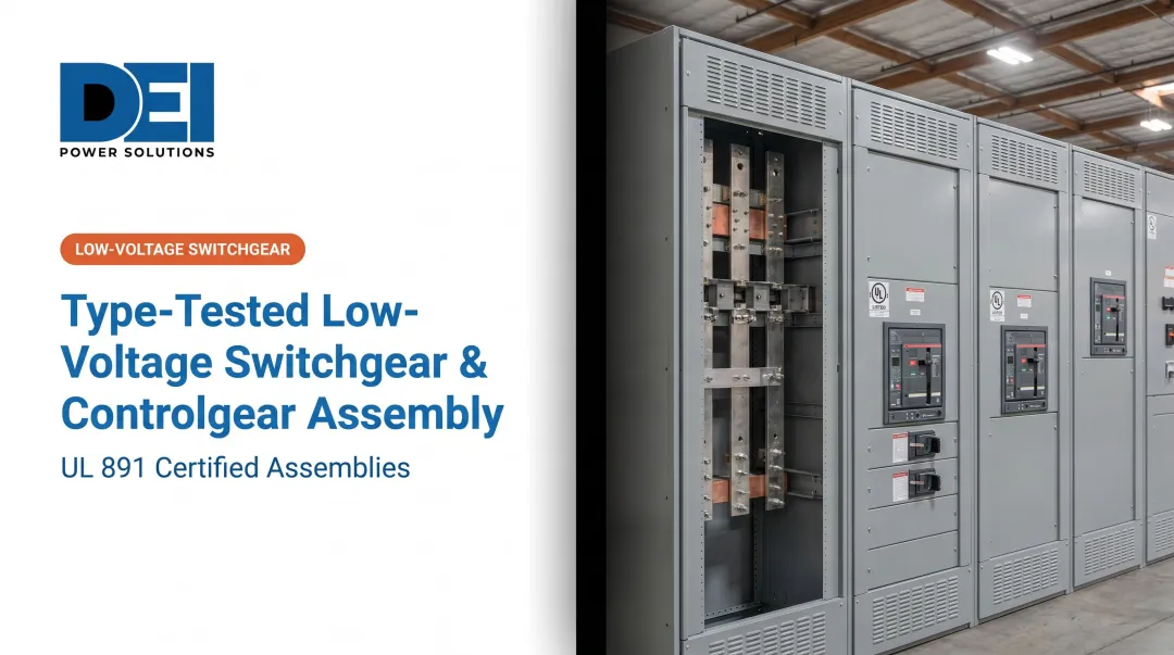
- UL 891-certified switchgear reduces field acceptance risk — factory testing validates the equipment before it arrives on-site
What Is Low Voltage Switchgear Testing?
Low voltage switchgear testing covers the electrical and mechanical verification procedures performed on assemblies operating at voltages up to 1,000V AC (or 1,500V DC per IEC standards). The goal is straightforward: confirm safe, code-compliant operation before and during service — catching manufacturing defects, installation errors, and degradation before they cause equipment failure, arc flash events, or personnel injury.
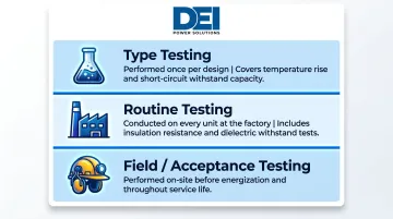
Testing falls into three distinct categories, each serving a specific purpose:
Type Testing — Performed once per product design by the manufacturer. Covers temperature rise tests, short-circuit withstand capacity, and mechanical endurance to verify the design meets all applicable safety and performance standards.
Routine Testing — Performed on every unit at the factory to catch defects in materials and workmanship. Per IEC 61439-1, every switchboard leaving the facility should pass insulation resistance and dielectric withstand tests before shipment.
Field/Acceptance Testing — Performed on-site before initial energization and throughout the service life. Confirms the equipment arrived undamaged, was installed correctly, and continues to operate within design specifications.
Governing Standards:
| Standard | Scope | Jurisdiction |
|---|---|---|
| IEC 61439-1 and IEC 61439-2 | Design verification, routine testing, and assembly requirements for LV switchgear | International |
| ANSI/NETA ATS | Acceptance testing specifications for new installations | North America |
| ANSI/NETA MTS | Maintenance testing specifications for in-service equipment | North America |
| NFPA 70E | Electrical safety requirements for personnel working on or near energized equipment | North America |
| UL 891 | Switchboard-specific factory compliance and construction requirements | North America |
Why Low Voltage Switchgear Testing Is Critical
Untested or poorly maintained switchgear creates direct safety and operational risks. Insulation breakdown, arc flash events, and protective device failures rank among the leading causes of electrical system outages and injuries in industrial and commercial settings.
An estimated 2,700 to 30,000 arc flash incidents occur annually in the U.S., with temperatures exceeding 35,000°F — nearly four times the sun's surface temperature, according to NFPA and OSHA data.
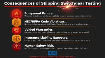
Operational and Compliance Consequences:
- Equipment failure — Undetected high-resistance connections cause overheating, insulation damage, and eventual failure
- NEC/NFPA code violations — Inadequate testing documentation exposes organizations to regulatory penalties
- Voided warranties — Manufacturers may refuse warranty claims if acceptance testing was not completed per published specifications
- Insurance liability exposure — Insurers increasingly require documented testing and maintenance programs
- Human safety risk — Personnel working near energized equipment face arc flash and electrocution hazards when protective devices fail
Uptime-Critical Environments:
In data centers, hospitals, and manufacturing plants where continuous power is essential, switchgear failures cause immediate, costly disruptions. When downtime costs reach $500,000 per hour, a single undetected fault can halt production, compromise patient safety, or take a data center offline. Systematic testing is the most direct way to prevent that outcome.
Key Types of Low Voltage Switchgear Tests
A complete LV switchgear testing program covers both electrical and mechanical verification. Each test targets a specific failure mode — no single test substitutes for the full sequence.
Insulation Resistance Testing (Megger Test)
This test measures resistance between conductors and ground using a megohmmeter at a minimum of 500V DC. It verifies that insulation has not degraded due to moisture, contamination, or mechanical damage.
IEC 61439-1 Requirements:
- Minimum acceptable value: 1,000 Ω/V relative to nominal circuit voltage
- For a 400V system: minimum 0.4 megohm (practical target: 0.5 megohm or higher)
ANSI/NETA ATS Requirements (More Stringent):
| Equipment Rating | Test Voltage | Minimum Resistance |
|---|---|---|
| 250V | 500V DC | 25 megohm |
| 600V | 1,000V DC | 100 megohm |
| 1,000V | 1,000V DC | 100 megohm |
For North American installations, apply NETA thresholds — they're approximately 167 times more stringent than IEC minimums for 600V systems.
Test Procedure:
- Measurements taken phase-to-phase and phase-to-ground
- All breaking devices in ON position
- Sensitive electronic devices (trip units, meters, PLCs) disconnected before testing
Dielectric Withstand Testing (Hi-Pot Test)
This test applies an elevated test voltage for one minute to confirm insulation can survive operational overvoltages without flashover or breakdown. It validates clearances, not material quality.
IEC 61439-1 AC Test Voltages:
| Rated Insulation Voltage (Ui) | AC Test Voltage (RMS) |
|---|---|
| ≤ 60V | 1,000V |
| 60V – 300V | 1,500V |
| 300V – 690V | 1,890V |
| 690V – 800V | 2,000V |
| 800V – 1,000V | 2,200V |
Procedure requirements to follow:
- Only perform after insulation resistance meets minimum thresholds
- Apply voltage gradually from 0V and return to 0V before switching off
- Limit test duration to 1 minute for acceptance testing per IEC 61439-1
- Test each pole to ground, between poles, and between separate circuits
Contact and Bolted Connection Resistance Testing (DLRO)
A low-resistance ohmmeter (DLRO) measures micro-ohm resistance through bolted bus connections, lugs, and joints to detect high-resistance connections caused by improper torque, corrosion, or material defects.
ANSI/NETA Acceptance Criteria:
- Flag any connection showing more than 50% deviation from the lowest similar reading
- Investigate or replace fuses deviating more than 15% from identical units
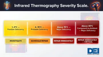
Complementary Technique — Infrared Thermography:
| Temperature Differential | Severity | Action Required |
|---|---|---|
| 1-3°C (component to component) | Possible deficiency | Investigate |
| 4-15°C | Probable deficiency | Repair as schedule permits |
| >15°C | Major deficiency | Repair immediately |
| >40°C (component to ambient) | Major deficiency | Repair immediately |
High Current Injection Testing (Trip Unit Verification)
This test injects high current through circuit breaker trip units at defined multiples of rated current to verify that breakers operate within manufacturer-specified time-current curves.
Standard Test Parameters:
- Long-time function: Typically tested at 300% of rated current per NEMA AB4
- Short-time function: Tested at manufacturer-specified multiples
- All three phases tested individually
- Trip times must fall within manufacturer's published tolerance bands or NETA Table 100.7 values
Results outside tolerance bands require investigation before energization. Inconsistent performance across phases points to mechanical wear or calibration drift — both must be resolved, not deferred.
Protective Circuit Continuity and Ground Resistance Testing
Protective Circuit Continuity (IEC 61439-1):
- Test current: Not less than 10A (AC or DC)
- Maximum resistance: 0.1 Ω between exposed conductive parts and protective conductor
- Confirms all metal enclosures and components are properly bonded
Ground Resistance Thresholds (ANSI/NETA ATS):
| Application | Maximum Resistance |
|---|---|
| Large commercial/industrial systems | 5 Ω |
| Generating stations | 1 Ω |
| Point-to-point (between equipment frames) | 0.5 Ω |
Values above 5 Ω for main grounding electrodes require investigation and repair before energization. Each of the five test types above addresses a distinct failure mode — together, they form the complete verification sequence referenced throughout this guide.
How to Conduct Low Voltage Switchgear Testing: Step by Step
Most field failures result not from unknown procedures but from shortcuts — skipping de-energization confirmation, rushing insulation tests before equipment has stabilized, or failing to document results per NFPA 70E and ANSI/NETA requirements. Most field failures result not from unknown procedures but from shortcuts — skipping de-energization confirmation, rushing insulation tests before equipment has stabilized, or failing to document results per NFPA 70E and ANSI/NETA requirements.
The five steps below walk through the complete testing sequence, from pre-test safety through final QC sign-off.
Step 1 – Pre-Test Safety and Preparation
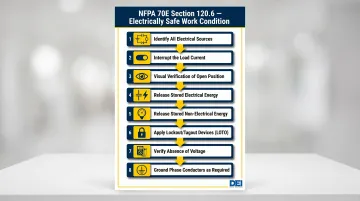
NFPA 70E Section 120.6 requires an 8-step Electrically Safe Work Condition (ESWC):
- Determine all possible sources of electrical supply (check drawings, diagrams, tags)
- Interrupt load current and open disconnecting devices for each source
- Visually verify disconnecting devices are fully open or draw-out breakers are in test position
- Release stored electrical energy — discharge capacitors (including VFDs and UPS systems), manage battery sources
- Release or block stored non-electrical energy (pneumatic, hydraulic, mechanical)
- Apply lockout/tagout (LOTO) devices per documented procedure
- Verify absence of voltage using adequately rated test instrument — live-dead-live method: verify instrument on known source, test each phase-to-phase and phase-to-ground, re-verify instrument
- Ground all circuit conductors before touching where induced voltages or stored energy may exist
Additional Pre-Test Steps:
- Identify and isolate solid-state components, electronic trip units, and measurement instruments that cannot withstand test voltages
- Review nameplate data against project drawings to confirm ratings, fuse sizes, and breaker types match specifications
- Ensure testing is performed only by qualified persons per NFPA 70E definition
Step 2 – Visual and Mechanical Inspection
Physical Condition Verification:
- Enclosures, busbars, insulators, and wiring for physical damage
- Correct labeling, clearances, and mounting distances
- Absence of shipping braces or foreign objects inside cubicles
- Clear ventilation openings and intact IP rating
IEC 61439-1 Minimum Clearances (Practical Recommendations for 690V Systems):
- Bare live parts to each other: 10 mm minimum
- Bare live parts to bodies/constructional components: 15 mm minimum
Mechanical Operation Checks:
- Interlocks, latches, draw-out mechanisms operate smoothly
- Door closures secure properly
- Circuit breaker racking mechanisms function without binding
- All required markings and documentation present
Step 3 – Insulation Resistance and Dielectric Withstand Tests
Before applying dielectric withstand voltage, insulation resistance results must confirm the equipment is ready. Advancing without this check risks damaging weakened insulation and voiding test records.
Sequence (Critical — Do Not Skip):
- Run insulation resistance tests first (phase-to-phase and phase-to-ground)
- Record all values before proceeding
- Only advance to dielectric withstand if insulation resistance meets minimum thresholds
- Apply dielectric test voltage in correct sequence:
- Each pole to ground
- Between poles
- Between separate circuits
- Ramp voltage from 0V and return to 0V before switching off to avoid switching overvoltages
- Limit test duration to 1 minute per IEC 61439-1 to avoid degrading insulation
Step 4 – Electrical Function and Protection Tests
Test Sequence:
- DLRO contact resistance measurements on bolted connections and bus sections end-to-end
- High current injection on circuit breaker trip units across all three phases
- Interlock verification by attempting closure on locked-open devices and attempting to open locked-closed devices
- Electrically operated breaker testing by applying voltage at secondary disconnects, operating the charging motor, and verifying closing/tripping sequences
- Control wiring insulation resistance (500V DC for 300V-rated cable, 1,000V DC for 600V-rated cable) with minimum acceptable values of 2 megohm
Step 5 – Documentation, Reporting, and QC Sign-Off
Required Documentation Elements:
- Technician name and date
- Equipment nameplate data
- Test voltages applied
- Pass/fail values for each test
- Comparison against manufacturer specifications or ANSI/NETA tables
Incomplete or undated records create compliance liability and make trend analysis impossible over time. ANSI/NETA requires individual inspection reports for each assembly — complete documentation also supports warranty claims, insurance audits, and future maintenance planning.
How DEI Power Helps You Get Testing-Ready
DEI Power's UL 891-certified switchboards arrive on-site already tested. DEI Power conducts factory routine testing — including insulation resistance and dielectric withstand — on every unit before shipment from the Ontario, California facility. With over 10 years of manufacturing experience as an approved Siemens OEM, these switchboards are engineered to meet ANSI/NETA acceptance criteria from day one, so field teams aren't starting from scratch.
Clear Documentation and Configuration Guidance
Every DEI Power order includes the documentation commissioning engineers need to complete ANSI/NETA acceptance testing efficiently: wiring diagrams, nameplate data, and component specifications. This eliminates guesswork and keeps field adjustments to a minimum.
Built for Time-Sensitive Projects
DEI Power's in-house manufacturing and rapid fulfillment capabilities deliver in-stock units in 3-5 business days with free shipping nationwide. Custom configurations (400A-4000A) ship in 4-6 weeks — fast enough to keep most project schedules intact. Starting with equipment that's already tested, documented, and code-compliant means fewer surprises when the commissioning clock is running.
Engineering Support When You Need It
DEI Power's in-house technical team assists with specification review, drawing coordination, and testing questions throughout the project lifecycle. For project-specific requirements or technical consultation, reach the team at sales@deipower.com or (866) 773-8050.
Frequently Asked Questions
How do you test switchgear?
Switchgear testing follows a structured sequence: visual and mechanical inspections first, then electrical tests including insulation resistance, dielectric withstand, contact resistance (DLRO), circuit breaker trip unit verification, and ground continuity. All results must be documented per ANSI/NETA ATS or MTS standards, compared against acceptance criteria, and signed off by qualified personnel.
What is a dielectric test in switchgear?
A dielectric withstand test applies elevated voltage across insulation for one minute — per IEC 61439-1 tables — to confirm clearances and insulation can handle electrical stress without flashover or breakdown. It must follow insulation resistance testing, not replace it; only equipment that passes insulation resistance thresholds should proceed to dielectric testing.
What is the switchboard inspection checklist?
A switchboard inspection checklist covers physical condition, nameplate verification, busbar clearances, bolted connection torque, wiring labeling, interlock operation, IP rating, and required documentation. ANSI/NETA ATS Section 7.1.A provides the detailed acceptance testing framework.
What is the difference between UL 891 and UL 1558?
UL 891 is the product safety standard for switchboards (dead-front distribution switchboards with bolt-in or plug-in branch devices and UL 489 molded-case breakers). UL 1558 applies to metal-enclosed low voltage power circuit breaker switchgear with draw-out UL 1066 power circuit breakers. They serve different applications and have different construction, clearance, and testing requirements.
What is the IEC standard for switchgear testing?
IEC 61439-1 and IEC 61439-2 govern design verification and routine testing of low voltage switchgear assemblies up to 1,000V AC or 1,500V DC. Coverage includes insulation resistance, dielectric withstand, protective circuit continuity, temperature rise, short-circuit withstand, and final inspection.
What is NFPA 70E for low voltage?
NFPA 70E is the Standard for Electrical Safety in the Workplace, covering safe work practices for energized low voltage equipment. It addresses lockout/tagout, arc flash hazard assessment, PPE selection, qualified person training, and the structured process for establishing an electrically safe work condition before testing or maintenance.