Introduction
When power distribution fails in an industrial facility, the consequences extend far beyond a temporary inconvenience: production lines halt, equipment sustains damage, and serious safety hazards emerge. For contractors, engineers, and facility managers, these aren't hypothetical scenarios. According to a 2025 ABB global study of 3,600 industrial decision-makers, 83% report that unplanned downtime costs at least $10,000 per hour — with 76% estimating losses up to $500,000 hourly. Disruptions are also frequent: 44% experience equipment-related interruptions at least monthly, while 14% face weekly stoppages.
Industrial power distribution differs fundamentally from commercial applications. It must accommodate high fault currents, variable load profiles from motors and automation equipment, harmonic disturbances from VFDs and rectifiers, and strict compliance requirements that demand deliberate engineering decisions, not off-the-shelf solutions.
A poorly coordinated protective device can shut down an entire production area when a single motor fails. Undersized transformers handling harmonic loads operate at 75% capacity, creating unexpected bottlenecks. These are predictable outcomes of inadequate design, not edge cases.
This article covers what industrial power distribution entails, the core components that comprise these systems, proven design principles for reliability and safety, common pitfalls that lead to costly downtime, and critical factors to evaluate when sourcing equipment for mission-critical installations.
TLDR:
- Industrial power distribution routes electricity from utility sources through transformers, switchgear, and panels to machinery, motors, and controls
- Main system types (radial, loop, open-bus) offer different tradeoffs between cost, redundancy, and uptime protection
- Reliable design requires detailed load analysis, protective device coordination, and properly rated switchgear with capacity headroom
- Safety compliance requires adherence to NEC (NFPA 70), NFPA 70E arc flash standards, and UL 891 switchboard certification
- Prioritize UL-certified components, BABA-compliant domestic manufacturing, and engineering support to avoid costly field adjustments
What Is Industrial Power Distribution?
Industrial power distribution is the electrical infrastructure that receives power from a utility grid or onsite generation source and routes it safely to machinery, motors, automation controls, and auxiliary systems within a facility. This differs from residential or light commercial distribution in scale, voltage levels, load types, and fault current demands. Where a commercial office building might draw steady, predictable loads, an industrial plant experiences large inrush currents during motor starts, harmonic distortion from variable frequency drives (VFDs), and sudden load changes that stress every component in the distribution chain.
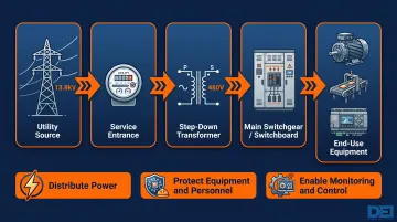
The typical flow starts when high-voltage utility power — often 13.8kV for large facilities — enters through the service entrance. Transformers step this down to usable levels: commonly 480V for industrial equipment in the U.S., though 4160V medium-voltage distribution serves larger motors and extends reach across sprawling campuses.
From the main switchgear or switchboards, power routes through panels and feeders to end-use equipment: conveyors, CNC machines, HVAC systems, PLCs, and process controls.
Every industrial power distribution system must perform three core functions:
- Distribute power across diverse loads with varying voltage and amperage requirements
- Protect equipment and personnel from faults by rapidly isolating failures before they cascade
- Enable monitoring and control of electrical flow to maintain system health and operational visibility
These fundamentals explain why industrial distribution demands engineered solutions rather than generic installations. Downtime, equipment damage, and safety failures are the real costs when distribution systems aren't designed for the environment they serve.
Key Components of an Industrial Power Distribution System
Transformers
Transformers step high-voltage utility power down to usable levels for different load types. Sizing transformer kVA ratings requires headroom for load growth — industry guidance recommends selecting at least 125% of anticipated maximum load. Industrial environments often require dry-type transformers for safety and maintenance advantages, particularly in occupied spaces where oil-filled units pose fire risks.
For facilities with VFDs, switching power supplies, or other nonlinear loads, K-rated transformers become essential. Per IEEE C57.110-2018, harmonic currents cause additional transformer heating. A standard transformer serving K-20 harmonic loads (typical for 6-pulse VFDs without reactors) operates at only 75% of nameplate capacity. K-13 rated transformers maintain 82% capacity under the same conditions. Specifying the wrong transformer type wastes capacity and creates a thermal failure risk that compounds over time.
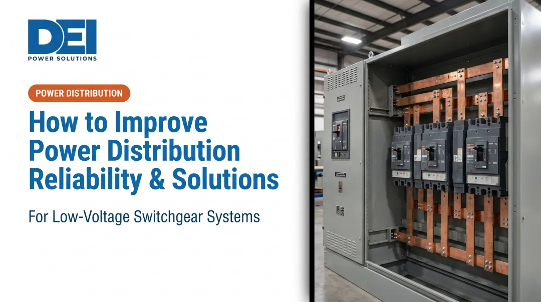
Switchgear and Switchboards
Switchgear and switchboards function as the central control and protection hubs, housing circuit breakers, busbars, protective relays, and metering equipment. Metal-clad switchgear handles medium voltage (above 1,000V) with drawout breakers and compartmentalized construction per IEEE C37.20.2. For low-voltage applications (1,000V and below), UL 891-listed switchboards provide the code-compliant backbone for safe distribution.
UL 891 certification confirms that equipment has undergone rigorous testing for short-circuit withstand (up to 200,000A), temperature rise, grounding integrity, and structural strength. Most Authorities Having Jurisdiction (AHJs) require UL listing for permit approval and field inspection. Non-listed or field-fabricated assemblies introduce liability, inspection delays, and potential voided warranties.
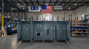
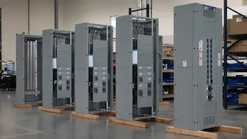
DEI Power manufactures UL 891-certified switchboards (400A to 4000A) using genuine Siemens components, with in-house production at their 50,000 sq. ft. Ontario, California facility. This vertical integration enables custom configurations (voltage levels, amperage ratings, physical layouts, and integration requirements) while delivering lead times of 4-6 weeks for built-to-order units and 1-5 business days for in-stock assemblies.
Distribution Panels and Motor Control Centers (MCCs)
Downstream from main switchboards, distribution panels divide power into branch circuits serving specific loads. Motor Control Centers (MCCs) centralize control over industrial motors (pumps, compressors, conveyors) with starters, overload protection, and contactors in modular "bucket" assemblies.
Per NEMA ICS 18-2001 and UL 845, MCCs rated up to 600V AC feature horizontal main bus (600A to 4,000A) and vertical bus (300A to 1,200A) for flexible motor control layouts. The plug-in unit design enables maintenance on individual motor circuits without de-energizing the entire MCC, reducing downtime during repairs.
Busbars and Feeder Conductors
Busbars distribute current within switchgear and panels using copper or aluminum conductors sized for both normal operating loads and fault current withstand. Feeder conductors carry power between equipment, with ampacity calculations per NEC Article 310 accounting for ambient temperature, conductor bundling, and insulation type. Undersizing conductors creates voltage drop issues that affect motor performance and control reliability; oversizing adds unnecessary cost. Proper calculation requires accurate load data and fault current analysis from the utility.
Protective Devices and Power Factor Correction
Circuit breakers, fuses, and protective relays isolate faults before they cascade through the system. NEC 110.9 requires that interrupting ratings equal or exceed available fault current at equipment line terminals. Poor coordination — where upstream devices trip before downstream devices isolate the fault — causes unnecessary shutdowns affecting healthy circuits.
Motor-heavy facilities require power factor correction to offset the reactive power drawn by inductive loads such as motors and transformers. Uncorrected reactive power increases utility demand charges and conductor losses. Two common correction approaches:
- Capacitor banks: Fixed or switched capacitors installed at the bus or load level to offset inductive reactive power
- Automatic Power Factor Correction (APFC) panels: Dynamic systems that switch capacitor stages in response to real-time load changes
Correcting power factor to 0.95 or higher reduces demand charges and improves voltage regulation under load.
What Are the Main Types of Industrial Power Distribution Systems?
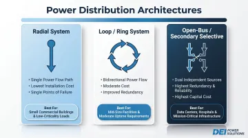
Three primary configurations dominate industrial power distribution, each with distinct tradeoffs:
Radial systems represent the simplest and lowest-cost approach. Power flows in one direction from the source through transformers and switchgear to end loads. Single points of failure exist — if a feeder fails, everything downstream loses power. Radial systems suit non-critical applications where occasional downtime is acceptable and budget constraints limit redundancy options.
Loop (ring) systems improve reliability by allowing power to flow from two directions. If one feeder segment fails, power routes through the alternate path. This requires additional switchgear and protective device coordination to handle bidirectional power flow, but significantly reduces single-point vulnerabilities. Loop systems balance cost and uptime for moderately critical operations.
Open-bus or secondary selective systems provide the highest redundancy for critical facilities where downtime cannot be tolerated. These architectures feature dual utility sources, redundant transformers, and automatic or manual transfer switches that maintain power during single-source failures or planned maintenance. The higher equipment and engineering cost is justified when an hour of downtime runs into six figures.
Choosing between these three architectures comes down to three factors:
- Criticality: How much does an hour of downtime actually cost your operation?
- Budget: What upfront investment in redundancy is justified against that risk?
- Footprint: Does the facility have physical space for dual sources, redundant transformers, and transfer switches?
A pharmaceutical line producing time-sensitive medications justifies secondary selective architecture. A warehouse running standard conveyors may work well with a radial system that includes strategic redundancy at critical nodes.
Design Principles for Reliability in Industrial Power Distribution
Load Analysis and Diversity Factors
Reliable design begins with detailed load flow analysis. This means inventorying all loads, calculating demand factors per NEC Article 220, and accounting for motor inrush currents and harmonic-generating equipment. NEMA MG1 standards indicate locked-rotor currents typically reach 6 to 8 times full-load current for NEMA Design B motors, depending on horsepower and code letter designation. Ignoring these transient demands leads to nuisance tripping during normal starts.
Harmonic-producing loads (VFDs, UPS systems, switching power supplies) require evaluation against IEEE 519-2022 limits. For systems at or below 69kV, voltage Total Harmonic Distortion (THD) must not exceed 5%, with current Total Demand Distortion (TDD) limits ranging from 5% for weak systems to 20% for robust systems with high short-circuit ratios.
Protective relays are particularly sensitive: 3-5% THD risks nuisance tripping. Triplen harmonics (3rd, 9th, 15th) sum in the neutral conductor, potentially pushing neutral conductor currents up to 300% of phase current on balanced three-phase systems.
Undersizing conductors or ignoring load diversity creates overloaded circuits, premature equipment failure, and production interruptions. With poor power quality and outages costing U.S. consumers $119-188 billion annually per EPRI/Primen research, accurate load analysis is financial risk mitigation, not an optional step.
Short-Circuit Calculations and Protective Device Coordination
Load analysis sets the foundation; short-circuit calculations determine whether your protective devices can actually handle a fault. Every protective device — breakers, fuses, relays — must be rated to interrupt available fault current at its location. NEC 110.9 explicitly requires interrupting ratings at nominal circuit voltage to at least equal the current available at equipment line terminals. Devices with inadequate ratings can explode under fault conditions, creating arc flash hazards and equipment destruction.
Equally critical is coordination: protective devices must trip selectively, isolating only the faulted circuit without cascading into unaffected areas. IEEE 242 (Buff Book) provides comprehensive guidance on protection and coordination principles. Poor coordination is a leading cause of unnecessary production shutdowns — a single motor failure trips a main breaker, halting an entire plant section and wasting materials, labor, and production capacity.
Redundancy Architectures
Once fault protection is addressed, the next design layer is continuity: ensuring faults or planned maintenance don't halt operations. Deploying redundant feeders, dual utility sources, or automatic transfer switches (ATS) accomplishes this — but redundancy must be engineered during initial design. Retrofitting it into existing systems costs considerably more and may be physically impossible due to space constraints.
Equipment compatibility is equally important for seamless source transfer. Mismatched voltage regulation or grounding schemes cause transfer disruptions even with ATS equipment installed. Coordinating with utility providers on dual-source configurations early in the design process prevents backfeed risks and avoids last-minute field changes.
Harmonic Mitigation and Power Quality
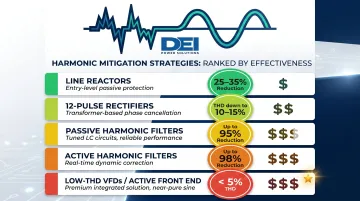
With redundancy established, power quality becomes the next reliability variable. Harmonic mitigation strategies range from simple passive solutions to real-time active correction:
- Line reactors (3-5%): Reduce THD by 25-35%, offering the simplest first-step solution for VFD installations
- 12-pulse rectifiers: Reduce THD to 10-15%, suitable for larger drives where line reactors prove insufficient
- Passive filters: Achieve up to 95% THD reduction through tuned LC circuits targeting specific harmonic frequencies
- Active harmonic filters: Deliver up to 98% THD reduction by injecting cancellation currents in real time
- Low-THD VFDs (Active Front End): Generate less than 5% THD at the source, eliminating downstream mitigation needs
Active filters provide maximum reduction but at greater cost and complexity. For most facilities, line reactors combined with K-rated transformers offer cost-effective protection.
Scalability in System Design
Industrial systems evolve — new production lines, equipment upgrades, facility expansions. Reliable design builds capacity headroom into busbar ampacity, transformer kVA, and conduit fill so growth doesn't require disruptive infrastructure overhauls. Specifying switchboards with spare breaker slots and knockout provisions for future feeders accommodates expansion without replacing core distribution equipment.
DEI Power's switchboards support this approach through customizable layouts and future-ready configurations. By planning for scalability upfront, facilities avoid the substantial costs and downtime associated with emergency capacity additions during peak production periods.
Safety Standards and Protective Design Considerations
Code Compliance — NEC (NFPA 70) and NFPA 70E
NFPA 70 (National Electrical Code, current edition 2026) governs installation requirements for U.S. industrial power systems. Key articles include:
- Article 110: General requirements for equipment installation, examination, approval, and workspace clearances
- Article 230: Service entrance conductors and equipment specifications
- Article 240: Overcurrent protection requirements for circuit breakers and fuses
- Article 408: Switchboards, switchgear, and panelboards construction and installation standards
NFPA 70E (current edition 2024) addresses electrical safety in the workplace, establishing requirements for arc flash hazard analysis, safe work practices, and personal protective equipment (PPE). Section 130.5 mandates arc flash risk assessment at intervals not exceeding 5 years or when system modifications occur. Equipment labeling per Section 130.5(H) must display nominal voltage, arc flash boundary, and incident energy or PPE category.
Violations of either standard create liability, inspection failures, and insurance complications — well beyond the immediate safety risks to personnel.
Arc Flash Hazard Analysis and Mitigation
Arc flash events release tremendous thermal energy: enough to cause severe burns, ignite clothing, and generate pressure waves that throw personnel across rooms. From 2011-2024, ESFI data based on BLS/OSHA records shows 26 arc flash fatalities among 2,070 total electrical workplace fatalities, with over 20,000 electrical injuries in the last decade.
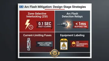
NFPA 70E requires documented arc flash hazard analysis for all energized work locations, which engineers typically calculate using IEEE 1584-2018 methods. Mitigation strategies include:
- Zone-selective interlocking (ZSI): Enables upstream and downstream devices to communicate, allowing the nearest device to clear faults in 0.1 seconds instead of backup time delays
- Arc flash detection relays: Detect arc light and overcurrent simultaneously, clearing faults in milliseconds
- Current-limiting fuses: Rapidly transfer fault current to parallel fuse elements, limiting let-through energy
- Proper equipment labeling: Ensures workers understand hazard levels and required PPE before performing energized work
Designing arc flash protection into the system from the start costs far less than retrofitting protection after incidents occur or when insurance audits identify deficiencies.
UL Certification and Equipment Standards
UL 891 certification for low-voltage switchboards confirms compliance with recognized safety standards through testing of short-circuit withstand, temperature rise, grounding/bonding integrity, and enclosure strength. The standard covers dead-front switchboards rated 1,000V or less with short-circuit ratings up to 200,000A.
Most AHJs require equipment listed by a Nationally Recognized Testing Laboratory (NRTL) — UL 891 is the predominant standard for low-voltage switchboards. Non-listed equipment creates inspection risk, permit delays, potential field rework, and voided manufacturer warranties. Any cost savings from non-certified assemblies disappear quickly when projects face stop-work orders or liability claims.
DEI Power's UL 891-certified switchboards come with a complete documentation package — pre-tested assemblies with engineering support available throughout the approval process.
Grounding, Bonding, and Surge Protection
UL certification addresses the equipment itself, but the surrounding installation must also be engineered correctly. Properly designed grounding and bonding systems provide low-impedance paths for fault current, enabling protective devices to operate as intended. Poor grounding creates touch and step potentials that endanger personnel, while inadequate bonding prevents effective fault clearing.
Surge Protective Devices (SPDs) installed at service entrances and sensitive equipment panels guard against transient overvoltages from lightning strikes or utility switching events. These devices clamp voltage spikes before they reach control systems, PLCs, and variable frequency drives — equipment particularly vulnerable to overvoltage damage.
Common Challenges in Industrial Power Distribution
Load Imbalance and Voltage Fluctuations
Unevenly distributed loads across phases cause neutral conductor overloading, increased losses, and reduced equipment life. Per NEMA MG1-14.35, a 3.5% voltage unbalance causes approximately 25% increase in motor temperature rise in the phase with highest current. Motor operating currents become unbalanced in the order of 6 to 10 times the voltage unbalance percentage, accelerating insulation degradation and shortening service life.
Voltage fluctuations from large motor starts, sudden load changes, or utility disturbances disrupt sensitive automation controls and PLCs. IEEE research indicates voltage sags alone cost U.S. industry $11-12 billion annually through equipment malfunctions, process interruptions, and production quality issues. Addressing load balance during the design phase — rather than retrofitting later — is the most cost-effective way to avoid these recurring losses.
Aging Infrastructure and Retrofit Complexity
Nearly 70% of U.S. power transformers exceed 25 years old per University of Wisconsin research, with much electrical infrastructure built 50-75 years ago, well beyond intended lifespans. Legacy switchgear often lacks arc flash ratings, has been modified in the field without proper documentation, or uses obsolete components that create protection gaps and compliance issues.
Retrofitting or replacing this equipment requires careful engineering to keep operations running. Facilities can't simply de-energize production areas for days at a time, so phased replacement strategies, temporary power provisions, and close coordination with operations teams add significant complexity and cost beyond the equipment itself.
Long Equipment Lead Times and Schedule Risk
Per DEI Power's May 2026 analysis, lead times for low-voltage switchboards have roughly doubled from pre-pandemic norms:
| Equipment | Pre-Pandemic Lead Time | Current Lead Time |
|---|---|---|
| Large LV Switchboards (1,200A+) | 20–30 weeks | 35–62 weeks |
Three factors are driving this pressure: surging data center demand (projected to account for 68% of U.S. load growth through 2030), $65 billion in grid modernization spending under the Infrastructure Investment and Jobs Act (IIJA), and single-source vulnerabilities for critical materials like grain-oriented electrical steel.
Choosing manufacturers with in-house production reduces schedule risk. DEI Power's domestic manufacturing and vertically integrated process enables 4-6 week lead times for custom builds and 1-5 business days for in-stock units — maintaining project schedules when extended delays from offshore or outsourced production could derail entire construction timelines.
What to Look for When Sourcing Power Distribution Equipment
UL Listing, Certifications, and Code Compliance
Verify UL listing (such as UL 891 for switchboards), confirm equipment is engineered to current NEC requirements, and check that manufacturers provide accurate documentation for AHJ review and commissioning. Non-listed equipment introduces inspection risk and potential field rework that costs far more than any initial savings.
Request submittal documentation, compliance certifications, and test reports before purchase orders. Manufacturers unwilling or unable to provide complete documentation raise red flags about product quality and regulatory compliance.
Engineering Support and Custom Configuration
Industrial projects rarely fit one-size-fits-all solutions. Look for manufacturers that build to project-specific voltage, amperage, layout, and integration requirements with in-house engineering support to prevent costly change orders and field adjustments.
DEI Power's engineering team assists throughout design, build, and delivery — covering specification review, load analysis, equipment sizing, and single-line diagram review to keep systems on spec and code-compliant.
Custom switchboards are built to exact project requirements, including:
- Voltage levels: 120/240V through 480Y/277V
- Amperage ratings: 400A to 4000A
- Physical layouts: wall-mounted or custom configurations
- Integration options: branch circuit monitoring and project-specific requirements
Domestic Manufacturing and Fulfillment Reliability
For federally funded or public infrastructure projects, Buy America Build America (BABA) compliance may be required per IIJA Section 70914. Iron and steel must be 100% U.S.-produced, while manufactured products require greater than 55% domestic component cost. Beyond regulatory compliance, domestic manufacturing means shorter lead times, easier quality oversight, and faster issue resolution.
DEI Power manufactures and assembles switchboards at their Ontario, California facility, ensuring BABA compliance for federal projects. Their vertically integrated process — from CAD engineering through metal fabrication, precision wiring, and testing — maintains strict quality control while enabling rapid fulfillment.
All orders ship free nationwide with delivery in 3-5 business days, including large switchboard assemblies. For time-sensitive projects, that combination of domestic production and predictable logistics removes one of the more common schedule risks before it starts.
Frequently Asked Questions
What is industrial power distribution?
Industrial power distribution is the electrical infrastructure that receives power from a utility source or onsite generator and safely routes it to machinery, motors, controls, and systems within an industrial facility at the voltages and capacities required by industrial-scale loads.
What are the main types of industrial power distribution systems?
The three primary configurations are radial (simplest, lowest cost, single points of failure), loop/ring (redundant path from two directions for improved uptime), and open-bus/secondary selective (highest redundancy for critical operations), with the right choice driven by your uptime requirements and budget.
What is a PDU and how does it work?
A Power Distribution Unit (PDU) distributes electrical power from a single input source to multiple output circuits, commonly used in data centers and industrial equipment rooms. Depending on the model, it may include metering, monitoring, and circuit protection, from basic strip units to intelligent/managed PDUs with remote control capabilities.
What equipment is used in most commercial and industrial power distribution applications?
Core equipment includes transformers, switchgear and switchboards, circuit breakers and protective relays, distribution panels and motor control centers (MCCs), and busbars or feeder conductors. Each component serves a distinct role in safely routing, protecting, and controlling power across the facility.
What safety standards apply to industrial power distribution systems in the U.S.?
Primary standards are NFPA 70 (National Electrical Code) for installation requirements, NFPA 70E for arc flash safety and electrical safe work practices, and UL listing standards such as UL 891 for switchboards that verify equipment meets safety and installation code requirements.
How do you ensure reliability in an industrial power distribution system?
Reliability starts with accurate load analysis, short-circuit calculations, and protective device coordination. Beyond that, redundant feeders, harmonic mitigation, and equipment sized with capacity headroom for future growth all contribute — supported throughout by code-compliant, UL-listed components.