Introduction
Unplanned downtime in a data center rarely traces back to a single catastrophic failure. More often, it starts with a design decision made early in the project — an undersized switchboard, a single-path distribution layout where two paths were needed, or redundancy that was never built in because it seemed like a cost to defer. By the time the gap becomes visible, fixing it means construction, shutdowns, and costly schedule delays.
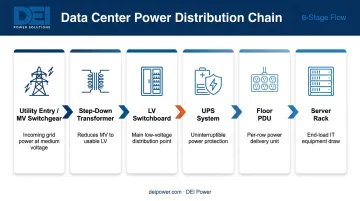
This guide covers the complete data center power distribution chain — from utility entry through medium-voltage switchgear, step-down transformers, LV switchboards, UPS systems, and PDUs down to the rack. It also covers layout topologies, redundancy strategies, and the best practices that engineering and facility teams can apply to real projects.
Whether you're designing a new build or auditing existing infrastructure for gaps, this guide is written for:
- Electrical engineers and power systems designers
- Data center architects and project managers
- Electrical contractors and EPC firms
- Facility managers responsible for uptime and compliance
Key Takeaways
- Power moves in a defined sequence — utility feed → MV switchgear → transformer → LV switchboard → UPS → PDU → rack — and each stage must be sized to support the next
- Layout topology (radial, primary-secondary selective, or A+B dual-bus) determines redundancy level and should align with your target Uptime Tier
- LV switchboards, UPS systems, and PDUs must be UL-listed and sized for both current draw and projected future load
- A+B dual-bus designs should keep each path loaded at 40–50% under normal conditions to allow full failover
- Redundancy must be designed in from day one — retrofitting it after construction is costly and operationally disruptive
How Power Flows in a Data Center: The Distribution Chain
Power distribution in a data center is sequential and hierarchical. Each stage steps voltage down, adds protection, and isolates loads so that a fault at one point doesn't cascade through the entire facility.
Utility Entry and Medium-Voltage Switchgear
Large data centers typically receive utility service at medium voltage, ranging from 13.8 kV up to 345 kV depending on facility size and location, according to CSE Magazine. Facilities drawing over 1 MW generally operate at MV to reduce transmission losses and enable the switchgear isolation needed for large-scale protection.
At the service entrance, revenue metering and MV switchgear with protection relays control and safeguard the facility's connection to the grid. Where utility voltage exceeds 13.8 kV, an initial step-down transformation at the service entrance brings it to a manageable level before it enters the building — setting up the main distribution transformation downstream.
Step-Down Transformation
Dry-type MV/LV transformers convert medium voltage to low-voltage distribution levels — typically 480V in North America and 400/415V in high-efficiency European and global designs. This stage is where load separation and electrical isolation happen. Different transformer secondaries can feed separate distribution paths, which is the physical foundation of A+B dual-bus redundancy.
LV Switchboards: The Core Distribution Hub
LV switchboards receive transformer secondary output and route power to UPS systems, mechanical loads (HVAC, cooling), and sub-distribution points. This is the most critical node in the chain: everything downstream depends on what happens here.
DEI Power's UL 891-certified switchboards are purpose-built for this role, available from 400A to 4000A across voltage configurations including 480V, 480Y/277V, 415/240V, and 208Y/120V. Built with genuine Siemens components and available in NEMA 1 or NEMA 3R enclosures, they can be custom-configured to match project-specific voltage, layout, and jobsite requirements.
Final Distribution: UPS, PDUs, and Racks
From the LV switchboard, power flows through:
- UPS systems — condition power and provide battery backup
- Floor-level PDUs — convert UPS output to branch circuits for rack rows
- RPPs or rack-mount PDUs (rPDUs) — deliver power to individual racks
- Server and networking equipment — the IT load itself
Each stage adds a layer of protection, metering, or conditioning that makes the overall system more manageable and resilient.
Data Center Power Distribution Layouts and Topologies
The topology you choose shapes everything downstream: redundancy level, maintenance flexibility, and your target Uptime Institute Tier. Get it wrong early, and no amount of downstream engineering fixes it.
Radial (Single-Bus)
Power flows from one source through a single set of distribution equipment to IT loads. Simple, cost-effective, and appropriate for Tier I/II or non-critical environments. The limitation is fundamental: any component failure in the single path causes an outage. There's no alternate route for power to travel.
Primary-Secondary Selective
When a single path isn't sufficient but full redundancy isn't in budget, Primary-Secondary Selective offers a middle ground. Two utility sources or transformer secondaries connect via interlocked tie breakers — if the primary fails, the tie breaker transfers load to the secondary. Reliability improves meaningfully over radial design, without the full cost of dual-bus architecture. This is a reasonable fit for mid-tier facilities where some redundancy is needed but the budget doesn't support full 2N.
A+B Dual-Bus (2N)
Two completely independent power paths — Path A and Path B — each with their own utility feed, transformer, UPS system, and PDU train. IT equipment with dual power supply units (PSUs) connects simultaneously to both paths.
Critical sizing rule: Each path should carry approximately 40–50% of total IT load under normal operation. HP's foundational data center power paper is explicit on this: loading above 50% per path means that if one path fails, the surviving path is overloaded. Size for failover, not just normal balanced operation.
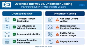
Overhead Busway vs. Underfloor Cabling
| Feature | Overhead Busway | Underfloor Cabling |
|---|---|---|
| Airflow impact | Zero floor plenum obstruction | Can block cooling airflow |
| Flexibility | Tap-off additions without shutdown | Reconfiguration requires downtime |
| Scalability | Add capacity incrementally | Full re-pull when layout changes |
| Modern preference | Increasingly preferred for AI-era DCs | Legacy approach, still common |
Data Center Dynamics notes that power distribution is evolving from RPP-heavy, underfloor cabling toward overhead busway — particularly in AI-driven builds where rack densities and layout changes happen frequently. Vertiv similarly confirms that underfloor cabling can block cooling plenums while overhead busway offers a zero-footprint, unrestricted cooling approach.
Key Power Distribution Equipment Explained
LV Switchboards
The LV switchboard is the central distribution point between transformers and downstream loads. It contains the main breaker, bus bars, branch breakers, and surge protection, controlling how power is split between UPS systems, mechanical equipment, and other sub-distribution circuits.
In the US, low-voltage switchboards must comply with NEC (NFPA 70) and carry UL 891 listing. UL 891 covers dead-front switchboards rated 600V or less, verifying that the equipment meets established safety and performance standards for commercial and industrial power distribution.
DEI Power manufactures UL 891-certified switchboards as a Siemens-approved OEM, with configurations available across the 400A–4000A range. Submittals and compliance documentation ship with each order, which simplifies inspection and project closeout.
From the switchboard, power flows downstream to UPS systems and sub-distribution equipment — each with its own design requirements.
UPS Systems
Double-conversion (online/VFI) is the standard topology for data center use. It provides complete electrical isolation between the utility input and IT load, voltage and frequency independent (VFI) per IEC 62040-3, so the output to critical equipment is clean regardless of what's happening upstream.
Battery technology is shifting. Uptime Institute reported that nearly half of operators had adopted lithium-ion for centralized UPS plants by 2021, up from roughly a quarter three years earlier. Li-ion offers higher power density, more charge/discharge cycles, and more predictable end-of-life capacity loss compared to VRLA. Fire risk considerations and different charging requirements make this a design decision worth evaluating carefully.
Floor-Level PDUs
Floor PDUs receive UPS output and convert it to branch circuits for rack rows. Key anatomy:
- Main input breaker
- Optional isolation transformer (for step-down or galvanic isolation)
- Branch circuit panelboard
- Surge protection and metering
Eaton's cabinet PDU line covers 50–500 kVA with inputs at 208/380/400/415/480/600V, three-phase. PDUs that include integral transformers allow for voltage step-down (480V to 208V, for example) at the row level — useful when the LV switchboard distributes at 480V but rack equipment runs on 208V.
RPPs and Rack-Level PDUs
Remote Power Panels (RPPs) sit between floor PDUs and individual racks. They provide localized branch circuit protection and make it possible to isolate and service individual rack rows without taking down a full PDU zone.
DEI Power's RPPs are available from 225A to 1200A, supporting up to 84 branch circuits, with optional branch circuit monitoring for real-time power visibility. Wall-mounted for space-efficient deployment in tight data center aisles.
Rack PDUs (rPDUs) come in four types:
| Type | Capability |
|---|---|
| Basic | Power distribution only, no visibility |
| Metered | Local current/voltage/power factor display |
| Monitored | Remote real-time monitoring and alerts via SNMP |
| Switched | Remote outlet control, reboot, outlet-level limits |
For any serious deployment, monitored rPDUs are the minimum. The ability to see per-rack load in real time is essential for capacity planning and preventing overloads.
Transfer Switches: ATS vs. STS
Automatic Transfer Switches (ATS) use electromechanical contactors to switch between normal and emergency power. Eaton's contactor-based ATS achieves transfer times of less than 150 ms, fast enough for most applications where UPS systems bridge the gap.
Static Transfer Switches (STS) use silicon-controlled rectifiers (SCRs) in opposing pairs. Vertiv's STS2 achieves standard interruption of less than ¼ cycle and fast undervoltage detection in under 4 ms, which matters for IT loads sensitive to brief power interruptions between sources.
Use STS where the priority is near-zero transfer time between redundant sources. ATS is appropriate where transfer time is less critical and cost constraints favor electromechanical design.
Redundancy Strategies for Data Center Power Distribution
N, N+1, and 2N: Mapped to Uptime Tiers
| Redundancy Model | Description | Uptime Tier Alignment |
|---|---|---|
| N | Exact capacity for full IT load, no spares | Tier I |
| N+1 | One additional backup component per subsystem | Tier II / Tier III |
| 2N | Full duplication of entire power chain | Tier III / Tier IV |
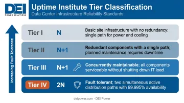
The Uptime Institute Tier framework defines expectations clearly:
- Tier I: Basic capacity. Maintenance or failure can impact the site.
- Tier II: Redundant components, but distribution path failures can still cause outages.
- Tier III: Concurrently maintainable — redundant components and redundant distribution paths, allowing maintenance without impacting the critical environment.
- Tier IV: Fault tolerant — an individual equipment failure or distribution path interruption will not impact operations.
The target Tier should be established at the start of the design process. It drives every downstream topology decision, from switchgear configuration to UPS sizing to generator paralleling.
Generator Integration
Generators integrate at the MV or LV distribution level, connected through ATS or STS, and must be sized to carry the full facility load. CSE Magazine notes that generators typically bring the standby system online within 10–30 seconds, with UPS battery providing the bridge.
For Tier-aligned designs, the fuel system topology must match the facility's Tier objective. Uptime Institute is explicit: the Tier rating is determined by the lowest-rated subsystem in the chain. Key generator design requirements include:
- Minimum 12 hours of fuel storage as Uptime's baseline for Tier-classified facilities
- N+1 or 2N generator capacity for larger installations requiring continuous availability
- Paralleling switchgear that allows individual generator sets to go offline for maintenance without reducing total capacity
Best Practices for Data Center Power Distribution Design
Design for Future Load Growth
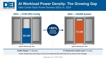
Schneider Electric notes that data center facility lifespans run 15–20 years, while IT equipment refresh cycles run 3–5 years. That mismatch creates pressure on power infrastructure that was designed for workloads that look nothing like what's running today.
AI workloads are accelerating this problem. Schneider cites ~40 kW/rack for 2023-era H100 GPU configurations and 72 kW/rack for 2024 GH200 systems — a density jump that most legacy distribution systems weren't built to handle.
Design recommendations:
- Specify switchgear and busway with capacity headroom for the next refresh cycle, not just current load
- Use overhead busway where possible — tap-offs can be added without shutdowns as density increases
- Choose modular UPS architectures that allow capacity addition without replacing the entire system
Enforce Code Compliance from Specification Through Commissioning
In the US, power distribution equipment must comply with NEC (NFPA 70), and low-voltage switchboards should carry UL 891 listing. Specifying listed and certified equipment from the start reduces the risk of field rejections, AHJ pushback, and insurance complications at closeout.
Compliance documentation requirements should be confirmed during the specification phase — not resolved at commissioning. Manufacturers who provide engineering support early can conduct specification reviews, coordinate submittals, and ensure correct system configuration before production, which cuts change orders and keeps schedules intact.
DEI Power's in-house engineering team handles this process end-to-end. Their switchboards carry UL 891 certification and EUSERC approval, meet UBC, CBC, and IBC seismic requirements, and are Buy America Build America (BABA) compliant for federally funded projects.
Implement Power Monitoring and Phase Load Balancing
Unbalanced three-phase loads increase neutral conductor stress and generate excess heat. Beyond the efficiency impact, a heavily imbalanced distribution system is harder to troubleshoot and harder to capacity-plan accurately.
Monitoring requirements by distribution level:
- Floor PDUs: Real-time phase load visibility, overload alerts
- RPPs: Branch circuit monitoring to track row-level consumption
- rPDUs: SNMP or Modbus-connected monitored units for per-rack visibility
Line-current readings are essential for three-phase PDU management, and real-time data should feed into SNMP, email alerts, or DCIM platforms. Per-rack visibility gives operators the information needed to catch overloads early, plan capacity additions accurately, and verify that power draw stays within design limits.
Frequently Asked Questions
What is the difference between a PDU and a switchboard in data center power distribution?
A switchboard distributes power from transformers to large loads — UPS systems, mechanical equipment, and sub-distribution panels — at the facility level. A PDU receives conditioned power from a UPS and distributes it to individual rack rows and IT equipment. They serve different functions at different points in the chain.
What redundancy level is recommended for mission-critical data centers?
Tier III requires at least N+1 redundancy with concurrent maintainability, while Tier IV requires full 2N (dual-bus) architecture for fault tolerance. The right level depends on your uptime requirements, budget, and target Tier classification — so establish that target before design begins, not after.
What does A+B dual power path mean in data center design?
A+B architecture uses two fully independent power paths — each with its own utility feed, transformer, UPS, and PDU — supplying IT equipment through dual PSUs. Under normal operation, each path carries 40–50% of load. If Path A fails, Path B carries the full load without interruption.
How is power distributed from the utility grid to a server rack?
The chain runs: utility → MV switchgear → step-down transformer → LV switchboard → UPS → floor PDU → RPP or rPDU → server rack. Each stage steps voltage down and adds protection, conditioning, or metering before passing power to the next level.
What is three-phase power and why do data centers use it?
Three-phase power uses three conductors offset by 120 degrees, creating a more constant power flow with less heat generation than single-phase. Eaton describes it as the most efficient method for distributing power over distance. Data centers rely on it because it handles continuous, high-density IT loads with greater efficiency and less infrastructure overhead.
What standards govern low-voltage switchboard design in US data centers?
Low-voltage switchboards in the US must comply with NEC (NFPA 70) and should be UL 891 listed — a certification that confirms the switchboard has been tested to safety and performance standards for commercial and industrial applications rated 600V or less.