Introduction
Most data center outages don't start on the server floor. They start in a room engineers and facility teams rarely visit until something goes wrong — the power distribution room.
According to the Uptime Institute's 2024 Annual Outage Analysis, power failures are the primary cause of 52% of significant outages, and 54% of those outages cost more than $100,000 to recover from. Sixteen percent exceeded $1 million. Those numbers aren't abstractions — they're the direct financial consequence of PDR design decisions made months or years before the failure.
Those costs trace back to a common pattern: the PDR gets treated as an afterthought. Switchgear gets shoehorned into undersized spaces, working clearances get compromised, and battery rooms end up sharing ventilation with switching equipment.
A room like that may pass permitting. It won't hold up under maintenance pressure or emergency response.
This guide breaks down PDR layout, equipment requirements, and the code standards that shape every design decision — so the room works as hard as the infrastructure it serves.
Key Takeaways
- The PDR is a dedicated, restricted space housing transformers, switchgear, UPS systems, and ATS units that condition and distribute power before it reaches the IT floor
- NEC Article 110.26 governs working clearances; violations are among the most common PDR inspection failures
- NEC Articles 700–702, NFPA 70E, and ANSI/TIA-942 set the compliance framework for distribution path design
- Engineer redundancy into the PDR itself: N+1 supports concurrent maintainability, while 2N delivers full fault tolerance
- UL 891 certification is the minimum standard for low-voltage switchboards in mission-critical PDRs
What Is a Data Center Power Distribution Room?
The power distribution room (PDR) is a dedicated, access-controlled space within a data center that receives utility power, conditions and steps it down to usable voltages, protects against outages, and distributes power downstream to IT loads and mechanical systems.
Physically separating the PDR from the server floor (white space) satisfies both functional and regulatory requirements. PDR equipment generates substantial heat, operates at voltages that create serious arc flash exposure, and must remain maintainable without interrupting IT operations. Mixing primary electrical infrastructure with server racks creates compliance problems and safety hazards that affect both operations staff and electricians.
Where the PDR Fits in the Distribution Hierarchy
The PDR is the first layer of power distribution. Utility medium voltage arrives at the service entrance, gets stepped down through transformers, passes through switchgear and UPS systems, and then flows outward to:
- Floor-level power distribution units (PDUs)
- Remote power panels (RPPs)
- Overhead busways or under-floor conduit systems
- Individual server rack PDUs
Every downstream component depends on decisions made in the PDR — which is why layout, equipment specifications, and clearances set here ripple through every tier of the distribution chain.
Key Equipment in a Data Center Power Distribution Room
Transformers
Utility power arrives at medium voltage — the DOE confirms electricity is generally distributed at 15 kV to 34.5 kV. Transformers step that voltage down to usable levels (typically 480V or 208Y/120V) for facility and IT loads.
For indoor PDRs, dry-type transformers are the common choice because they use air for dielectric clearance rather than liquid coolant, which eliminates the need for liquid containment infrastructure inside the building. Per NEMA's data center transformer guide (NEMA US 80017-2023), most distribution transformers in data center applications are designed with impedance in the 2% to 8% range — a specification that directly affects downstream fault current calculations and switchboard ratings.
Switchboards and Switchgear
The low-voltage switchboard is the distribution hub of the PDR. It receives stepped-down power from the transformer and splits it to discrete load groups:
- IT floor feeders
- Mechanical and HVAC systems
- Lighting and convenience circuits
- Emergency circuits (classified under NEC Articles 700–702)
UL 891 is the standard for low-voltage switchboards; UL 1558 covers metal-enclosed low-voltage power circuit breaker switchgear assemblies. These are distinct standards for different equipment types. Don't treat them as interchangeable when specifying.
DEI Power manufactures UL 891-certified switchboards configured to specific voltage, amperage, and layout requirements for data center PDRs. Their product line covers 400A to 4000A across seven voltage configurations (including 480V, 480Y/277V, and 208Y/120V), with NEMA 1 or NEMA 3R enclosure options. Custom configurations — specific section counts, feeder breaker arrangements, and metering provisions — are available with in-house engineering support. Most custom orders ship within 4–6 weeks; in-stock units ship in 3–5 business days.
Automatic Transfer Switches (ATS)
The ATS detects utility power loss and transfers the load to a generator or alternate utility feed. Per UL 1008, transfer switch equipment is rated up to 1,000V for use in non-hazardous locations.
Positioned between the utility service entrance and the main switchboard, the ATS must be rated and coordinated with generator capacity before switchboard sizing is finalized. Transfer timing is governed by NFPA 110 Type classification, which defines the maximum allowable seconds without acceptable power at the load terminals — Type 10 (10-second transfer) is the common reference for NEC emergency system applications.
UPS Systems
UPS systems supply conditioned, battery-backed power to critical IT loads during the interval between utility failure and generator startup. UPS units are often housed in or directly adjacent to the PDR.
Battery strings — whether VRLA or lithium-ion — introduce specific infrastructure requirements that must be addressed at the design stage, not after construction:
- Separately ventilated space per NFPA 70E Article 320 (batteries and battery rooms)
- Dedicated HVAC sized for battery heat dissipation
- Structural floor loading rated for battery cabinet weight
- Retrofitting any of these after construction is expensive and often requires structural modifications
Main PDUs and Remote Power Panels
Large cabinet-style PDUs in the PDR receive power from switchboards and distribute it via floor whips or overhead busways. These are distinct from the rack-mounted PDUs on the server floor.
Downstream of the PDR switchboard, remote power panels (RPPs) handle structured branch circuit distribution. DEI Power's RPPs support 225A to 1200A input ratings with up to 84 branch circuits per panel, available in multiple voltage configurations. Wall-mounted units keep the white space clear of floor-standing distribution equipment — a practical advantage in hyperscale and enterprise deployments where every square foot of raised floor carries a cost.
Power Distribution Room Layout: Zones, Clearances, and Flow
Equipment Zoning
Every PDR should be divided into functional zones that mirror the power flow sequence. Mixing equipment types in a single undifferentiated space creates maintenance conflicts, code violations, and unnecessary arc flash exposure.
| Zone | Equipment | Key Consideration |
|---|---|---|
| Service Entrance / Transformer Zone | Utility service, transformers | Medium-voltage isolation, clearance from LV equipment |
| Low-Voltage Switching Zone | Switchboards, ATS | Primary distribution hub, NEC 110.26 clearances |
| UPS Zone | UPS modules | Adjacent to LV switching; isolated from battery area |
| Battery Room | Battery strings | Dedicated ventilation, NFPA 70E Article 320 compliance |
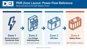
Separating these zones reduces cross-zone arc flash exposure and allows one section to be de-energized for maintenance while others remain live.
NEC Working Clearances
NEC Article 110.26 establishes non-negotiable minimums for working space around electrical equipment. For equipment under 1,000V:
- Minimum working space width: 30 inches, or equipment width — whichever is greater
- Minimum headroom: 6.5 ft from floor or platform
- Depth (Table 110.26(A)(1)):
- 0–150V: 3 ft for all three conditions
- 151–600V: Condition 1 = 3 ft | Condition 2 = 3 ft 6 in. | Condition 3 = 4 ft
The dedicated equipment space extends from the floor to 6 ft above the equipment (or structural ceiling, whichever is lower) and must be free of piping, ducts, and all foreign equipment. This zone protects the working space from overhead mechanical systems — a common conflict in tight mechanical/electrical rooms.
Clearance violations rank among the most frequent PDR design errors — and they're usually caught during inspection, after equipment is already positioned and structural elements are fixed.
Egress and Physical Security
Per NEC 110.26(C)(2), equipment rated 1,200A or more and over 6 ft wide requires one entrance and egress at each end of the working space — minimum 24 inches wide and 6.5 ft high. This ensures personnel can exit away from an arc flash event rather than retreating toward it.
Additional access requirements:
- PDR doors must swing outward to support emergency egress
- Access should be card-controlled, limited to qualified electrical personnel
- The room must not be used as a passageway or storage area (NEC 110.26)
Power Flow Orientation
Lay out equipment in a sequence that mirrors the one-line diagram — utility entry → transformer → ATS → main switchboard → UPS → outgoing distribution panels — in a consistent directional flow (left-to-right or front-to-back). A logical physical sequence:
- Reduces cross-cabling between distribution zones
- Simplifies troubleshooting during live maintenance
- Makes the room navigable for personnel who didn't design it
Design Requirements and Code Compliance
NEC Article 110 Requirements
Beyond clearances, NEC Article 110 establishes environmental and structural baselines:
- Illumination: Dedicated lighting sufficient for safe work without supplemental lighting
- Headroom: Minimum 6.5 ft in working spaces
- Room use: No storage, no passageways — the electrical room serves one purpose
These are minimums. Larger data center projects routinely exceed them, particularly for illumination levels and headroom, where standard commercial ceiling heights create comfortable working conditions.
Emergency and Standby System Classification (NEC Articles 700–702)
Load classification determines how circuits must be wired, separated, and tested within the PDR:
- Article 700 (Emergency Systems): Illumination and power for life safety when normal power fails
- Article 701 (Legally Required Standby): Selected loads beyond emergency systems
- Article 702 (Optional Standby): Other premises wiring not covered by 700 or 701
Each classification carries specific wiring separation requirements and transfer switch ratings that must appear in the PDR design and one-line diagram. Getting this wrong affects both inspection approval and insurance coverage.
NFPA 70E: Arc Flash Analysis
NFPA 70E requires an arc flash hazard analysis for all energized equipment in the PDR. The analysis determines:
- Incident energy levels at each piece of equipment
- Arc flash protection boundaries
- Required PPE categories (arc ratings of 4, 8, 25, and 40 cal/cm²)
Results must be documented on equipment labels and influence room layout. High-incident-energy switchboards may require additional working distance that wasn't accounted for in the original floor plan. Run the analysis before finalizing equipment placement — not after.
ANSI/TIA-942 Rated Infrastructure
ANSI/TIA-942 defines four infrastructure rating levels with direct implications for PDR design:
| Rating | Infrastructure Level | Distribution Path Requirement |
|---|---|---|
| Rated-1 | Basic | Single path, non-redundant |
| Rated-2 | Redundant Capacity | Redundant components, single path |
| Rated-3 | Concurrently Maintainable | Multiple paths; one active, one standby |
| Rated-4 | Fault Tolerant | Multiple active independent paths |
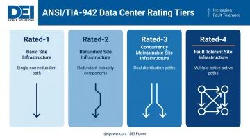
Rated-3 and Rated-4 facilities require multiple independent power distribution paths originating from the PDR — meaning more switchboards, additional ATS units, and dedicated physical space for parallel infrastructure.
Switchgear Certification
When specifying switchboards, require UL 891 listing (low-voltage switchboards) or UL 1558 (metal-enclosed LV power circuit breaker switchgear) to confirm equipment has been independently evaluated. These certifications address short-circuit withstand, dielectric integrity, and construction standards.
Specifying certified equipment from the start reduces change orders and keeps inspection approvals on schedule. DEI Power's UL 891-certified switchboards are built with Siemens components, manufactured in Ontario, California, and ship with submittals and compliance documentation included. Their in-house engineering team can review specifications prior to production to confirm the configuration meets project requirements.
Redundancy Strategies Built Into the PDR
N+1 vs. 2N at the Distribution Layer
Redundancy at the distribution layer means independent paths from the PDR to critical loads — a backup generator alone doesn't deliver that. The distinction matters because it determines how much parallel equipment and routing space your PDR must physically accommodate.
- N+1: One additional component above the minimum required. A single fault takes one component offline but the system continues operating. Appropriate for Tier III / Rated-3 concurrent maintainability.
- 2N: Complete mirroring — two fully independent distribution paths, each capable of carrying the full load. Required for Tier IV / Rated-4 fault-tolerant operation.
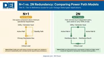
Both approaches require physical space in the PDR for parallel equipment and routing. That spatial commitment also shapes every downstream component decision — including bypass provisions for each piece of critical gear. Designing for N+1 and then upgrading to 2N later almost always requires significant reconstruction.
Maintenance Bypass Provisions
Every critical piece of equipment in the PDR — UPS systems, main switchboards — needs a maintenance bypass path. This allows individual components to be de-energized and serviced without interrupting the load.
Each bypass path requires:
- Bypass switches and interlocked transfer schemes
- Physical working space for technicians alongside the bypass equipment
- Coordination with the one-line diagram and labeling scheme
Retrofit bypass installations rarely work without a full planned outage — and even then, the structural constraints often make them cost-prohibitive. Build bypass provisions into the design from the start.
Fault Isolation and Load Separation
Separate IT critical loads from mechanical and facility loads at the PDR level. A fault or planned shutdown on a mechanical feeder should never cascade to the IT distribution path.
Operational requirements that support fast fault isolation:
- Clear, permanent circuit labeling on all panels and feeders
- Color-coded cable management consistent with the design documents
- Current one-line diagram posted inside the room and available digitally
- Documented load assignments updated when circuits are added or modified
Frequently Asked Questions
What is a power distribution room in a data center?
A PDR is a dedicated, access-restricted space housing the primary electrical infrastructure — transformers, switchgear, UPS systems, and ATS units — that receives utility power and distributes it to IT and facility loads throughout the facility. It is physically separated from the server floor for safety and maintenance isolation.
Where do data centers get power from?
Data centers receive utility power at medium voltage (15 kV to 34.5 kV per DOE distribution standards) and step it down on-site via transformers for low-voltage distribution to IT and mechanical loads. Diesel or gas generators and UPS battery systems cover backup power during utility outages.
What equipment is in a data center power distribution room?
The primary equipment includes utility service entrance components, dry-type transformers, low-voltage switchboards, automatic transfer switches, UPS modules, battery strings, and floor-level PDUs or remote power panels — all housed in a secure, code-compliant enclosure.
What are the NEC requirements for a data center power room?
NEC Article 110.26 governs working clearances, headroom (minimum 6.5 ft), and dedicated equipment space. Articles 700–702 classify emergency and standby system wiring. NFPA 70E requires an arc flash hazard analysis for all energized equipment in the room.
How is the PDR different from the server room?
The PDR houses primary electrical infrastructure and is restricted to qualified electrical personnel; the server room (white space) houses IT racks and is accessed by IT operations staff. Physical separation is required under NEC and NFPA 70E for arc flash safety and maintenance isolation.
What size should a data center power distribution room be?
PDR size depends on power capacity, equipment count, and NEC 110.26 clearance requirements on all required sides of each piece of equipment. Always design for planned expansion — retrofitting equipment into an undersized room typically forces a full layout redesign.