Introduction
Power distribution architecture is where data center reliability is won or lost. Every design decision — from how utility power enters the facility to how it reaches the server rack — creates downstream consequences that are difficult and expensive to reverse once construction is underway.
Most engineering and facility teams understand individual components well enough. What's harder to see is how those components interact as a system — and how a wrong decision at one layer cascades into failures at every layer below it.
This guide covers the complete power path from utility entry to server rack, the function of each distribution layer, redundancy design models, and the specification decisions that prevent costly rework — particularly as AI workloads drive rack densities past 30–50 kW and expose the limits of traditional architecture assumptions.
Key Takeaways
- Power moves through a fixed hierarchy — from utility grid through transformers, switchboards, UPS, and PDUs — before reaching server racks
- Redundancy must be engineered at the system level, not the component level. A single unprotected layer breaks the entire chain.
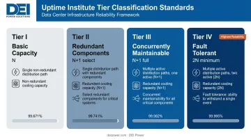
- Uptime Institute Tier classification (I through IV) determines which redundancy model the architecture must support
- Non-UL 891-certified switchboards at the LV hub create code compliance gaps and real AHJ rejection risk
- AI rack densities reaching 80–90 kW per rack are forcing zone-based distribution strategies that traditional single-density designs can't accommodate
How Power Flows Through a Data Center
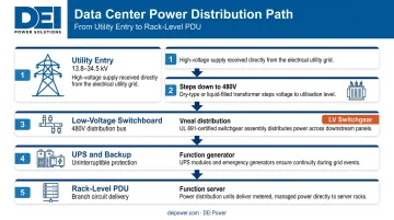
Data center power distribution is a sequential, cascading system. Power enters at medium voltage, gets stepped down through multiple transformation stages, and arrives at IT equipment as clean, regulated low-voltage power. Every layer in that path affects every layer below it — which is why design decisions at the utility entry point ripple all the way down to the rack.
Layer 1: Utility Entry
Power arrives via medium-voltage feeders, typically at 13.8 kV or 34.5 kV, according to Eaton's AI data center power paper. Primary medium-voltage switchgear at this layer provides fault protection and isolation. Tier III and IV facilities routinely require dual utility feeds — a second utility connection is a baseline design requirement at these classifications, not an optional upgrade.
Layer 2: Transformation
Medium voltage steps down to utilization voltage — typically 480V 3-phase in North America — through unit substation transformers. Transformer sizing directly determines downstream capacity; undersizing here creates a constraint that can't be solved at any lower layer. Transformer redundancy at this stage is what makes N+1 and 2N designs feasible further down the chain.
Layer 3: Low-Voltage Distribution
The main low-voltage switchboard receives power from the transformer secondary and routes it to UPS systems, mechanical loads, lighting, and other facility branch circuits. This is the central distribution hub — where circuit protection, metering, and load routing converge. Switchboard specification errors at this layer affect every downstream circuit.
Layer 4: Backup and Conditioning
UPS systems condition power and provide ride-through during generator startup — Schneider Electric's data center distribution white paper notes approximately 15 minutes of UPS autonomy at full load as a common design target. Automatic transfer switches manage the transition between utility and generator power, and NFPA 110 Type 10 requires generators to restore power within 10 seconds.
Layer 5: Rack-Level Distribution
Power reaches PDUs at the row or rack level, which distribute to individual servers, storage, and networking gear. Intelligent PDUs add outlet-level metering, load balancing, and remote management — in high-density environments above 10 kW per rack, that granularity is what prevents tripped breakers from becoming unplanned outages.
Key Components of the Distribution Chain
Medium-Voltage Switchgear
Medium-voltage switchgear receives utility power and routes it to the facility's transformer banks. Two primary types apply to data center applications:
- Metal-clad (IEEE C37.20.2): Electrical components in separate metal compartments — higher isolation, better suited for facilities requiring frequent maintenance access
- Metal-enclosed (IEEE C37.20.3): Components may share compartments — simpler construction, appropriate where maintenance isolation is managed through other means
Key specification factors include interrupting capacity, protection relay sophistication, and fault isolation speed. Microprocessor-based protective relays provide the coordination precision needed to isolate faults without tripping unaffected circuits — essential in facilities where upstream faults must not cascade to IT loads.
Low-Voltage Switchboards
The low-voltage switchboard is the central LV distribution hub. Under NEC Article 408, switchboards must meet specific construction and installation requirements. UL 891 is the accepted product safety standard for dead-front switchboards in commercial and data center applications — UL Solutions confirms it as the most common North American standard for this equipment category.
NEC 408.6 requires switchboards to carry a short-circuit current rating (SCCR) not less than the available fault current at the installation point. Getting this wrong means the switchboard fails inspection.
Custom-configured switchboards — matched to the specific voltage, amperage, and physical layout of the project — are the practical answer to avoiding field modifications and compliance gaps. DEI Power manufactures UL 891-certified switchboards from 400A to 4000A across seven voltage configurations (including 480V, 480Y/277V, and 415/240V), built to project specifications from their Ontario, California facility. Their status as a Siemens Approved OEM means the components inside those assemblies aren't generic substitutions — traceability and consistency matter when AHJ inspectors are reviewing submittals.
UPS Systems
UPS systems are the power conditioning and ride-through layer. For large data centers, double-conversion (online) topology is the standard choice — it provides zero transfer time to battery, continuously isolating IT equipment from grid anomalies including voltage sags, frequency deviations, transients, and sustained outages. Line-interactive systems condition voltage but don't provide the same continuous isolation.
Large-facility deployments typically use modular three-phase UPS configurations, where capacity can be added in blocks without replacing the entire system.
Backup Generators
Diesel generators carry the full critical load during prolonged outages. Key design parameters:
- Sizing: Generator capacity must cover the full critical load plus a growth margin; N+1 generator redundancy is driven by Tier requirements, not a universal rule
- Transfer timing: NFPA 110 Type 10 mandates power restoration within 10 seconds
- Parallel operation: Larger facilities require generators capable of synchronized parallel operation for load sharing and redundancy
- Fuel storage: Runtime requirements vary by project and AHJ — consult NFPA 110 classifications for the applicable Level and Class requirements
Power Distribution Units (PDUs)
Intelligent PDUs at the row and rack level determine whether operators can balance loads, detect circuit overloads before they cause outages, and support hot-swap scenarios without impacting live equipment. In high-density environments, outlet-level switching and remote management APIs are standard requirements, not optional upgrades.
DEI Power's Remote Power Panels (RPPs), available from 225A to 1200A with up to 84 branch circuits and optional branch circuit monitoring, serve as the intermediate distribution point between the main switchboard and rack-level PDUs, a position that becomes operationally significant in AI compute zones where load density and circuit granularity are tightly managed.
Redundancy Architecture: Choosing the Right Model
Redundancy design is the most consequential architectural decision in data center power planning. It determines Tier classification, capital cost, operational complexity, and achievable uptime SLAs. And it only works when designed at the system level — across every layer from utility entry to the rack, simultaneously.
N+1 Redundancy
N+1 provides one additional unit of capacity beyond what active loads require. Three generators where two carry the load, three UPS modules where two handle full capacity.
- Trade-off: Lower capital cost than 2N, but the facility is exposed to concurrent failures during maintenance windows
- Appropriate for: Uptime Institute Tier II and Tier III facilities
- Risk profile: A component failure during planned maintenance on the spare creates a single point of failure
2N Redundancy
2N creates two completely independent, isolated power paths — each capable of carrying 100% of the load independently. This requires mirrored infrastructure from utility entry to the server rack:
- Dual utility feeds
- Dual transformer banks
- Dual UPS strings
- Dual switchboard lineups
- Dual PDUs at the rack
The Uptime Institute defines Tier IV as fault-tolerant — a single failure or maintenance event must not impact the IT load. That requirement makes 2N the minimum for Tier IV. Many hyperscale deployments operate at 2N+1. Dual-corded server power supplies are the rack-level counterpart that makes 2N distribution architecture fully effective.
Concurrent Maintainability
Redundancy without concurrent maintainability is incomplete architecture. Any component in the system must be removable for maintenance without interrupting the live power path. This isn't optional — it's what separates Tier III from Tier II.
Practical requirements cover the full distribution chain:
- UPS systems: Maintenance bypass circuits allow the UPS to be taken offline without dropping the load
- Switchboards: Isolation switching permits breaker and bus work without de-energizing downstream circuits
- Generators: Transfer switching must support manual or automatic transfer so generator maintenance doesn't expose the facility to a single-path risk
Each of these requirements maps directly to the Tier classification your facility targets. The table below summarizes the relationship.
Tier Mapping Summary
| Tier | Classification | Redundancy Model |
|---|---|---|
| Tier I | Basic Capacity | N (no redundancy) |
| Tier II | Redundant Capacity Components | N+1 at select layers |
| Tier III | Concurrently Maintainable | N+1, fully concurrent |
| Tier IV | Fault Tolerant | 2N minimum |
Critical Design Considerations
Voltage Selection
Voltage level is a foundational decision with downstream consequences for transformer sizing, cable sizing, transmission losses, and PDU compatibility:
- 208V: Common in legacy installations and lower-density deployments; higher transmission losses at equivalent load
- 480V: Standard for North American data center distribution; supports higher-density loads with reduced conductor sizing requirements
- 415/240V: Used in hyperscale and international facilities; Schneider Electric's high-efficiency AC distribution research supports this approach as a way to reduce conversion steps and improve efficiency
The voltage choice made at the transformer secondary propagates through every downstream component specification. Changing it after construction is a major infrastructure project.
UL Certification and Code Compliance
NEC Article 408 governs switchboard construction and installation. UL 891 certification is the product standard that confirms a switchboard meets those requirements.
Specifying UL 891-certified equipment from the start eliminates two specific risks:
- AHJ rejection — Inspectors in most jurisdictions require listed equipment per NEC 110.3(B). Non-listed switchboards fail inspection and require replacement or costly field modification.
- SCCR mismatches — NEC 408.6 requires SCCR ratings not less than available fault current. The available fault current depends on the upstream transformer capacity and impedance — a calculation that must be done for each installation, not copied from generic tables.
These compliance requirements also have scheduling consequences. Custom switchgear from some suppliers carries lead times of 12–20 weeks, which can push a project past its energization date. Suppliers with in-house manufacturing — DEI Power builds custom switchboards in 4–6 weeks with delivery in 3–5 business days — offer a practical buffer against that risk.
Capacity Planning and Growth Headroom
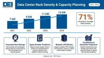
Data centers consistently underestimate load growth. AFCOM data from Omdia shows average rack density rose from 7 kW per rack in 2021 to 12 kW by 2024 — a 71% increase in three years.
Design strategies that accommodate growth without full infrastructure replacement:
- Specify switchboard bus ratings above day-one load requirements
- Include spare breaker positions in the initial switchboard layout
- Use modular UPS configurations that accept capacity blocks
- Size transformer and generator capacity with expansion in mind
The specific growth margin appropriate for a project depends on the facility's planned use, expected tenant mix, and AHJ requirements — not a universal percentage rule.
Planning for High-Density and AI Workloads
Standard data center racks average near 9 kW, up from 8.3 kW, according to the Uptime Institute's 2025 Global Data Center Survey. AI training racks are a different category entirely — Uptime Institute Journal reports standard AI training racks operating within 80–90 kW, roughly 10x the general facility average.
Traditional uniform distribution architectures can't serve both populations efficiently.
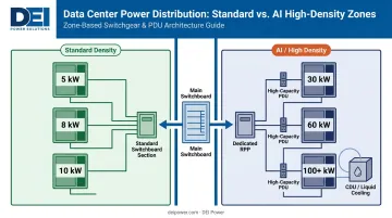
Power Density Zoning
The practical solution is zone-based architecture: separate high-density electrical zones for AI/GPU clusters from standard-density white space. This requires:
- Dedicated branch circuits sized for 30–100+ kW per rack rather than the 5–10 kW assumption baked into most legacy distribution designs
- Higher-capacity PDUs with granular current monitoring at the circuit level
- Independent switchboard sections or dedicated remote power panels for AI zones, allowing high-density areas to scale without triggering full infrastructure upgrades in adjacent standard-density areas
DEI Power's RPP lineup — up to 1200A with 84 branch circuits and branch circuit monitoring — is built for exactly this intermediate distribution role, sitting between main switchboards and high-density rack PDUs in AI compute and GPU cluster environments.
Cooling-Power Co-Design
Every high-density rack carries an equivalent cooling load that needs dedicated electrical circuits. Liquid cooling infrastructure for AI racks — coolant distribution units (CDUs), pumps, distribution manifolds — adds electrical load that must be factored into switchboard branch circuit planning from the start.
That CDU demand is real load competing for switchboard capacity. Designing power distribution without accounting for cooling infrastructure creates branch circuit conflicts during commissioning that are expensive to resolve after construction.
Frequently Asked Questions
What is the standard power distribution architecture for a data center?
The standard path runs: utility entry → medium-voltage switchgear → step-down transformers → low-voltage switchboards → UPS systems → PDUs → server racks. The exact configuration varies by Uptime Institute Tier classification — Tier I operates with no redundancy while Tier IV requires fully mirrored, fault-tolerant infrastructure at every layer.
What is the difference between N+1 and 2N redundancy in data center power?
N+1 adds one backup unit to critical systems — enough to survive a single failure under normal conditions. 2N creates two fully independent power paths, each capable of carrying 100% of the load, which eliminates single points of failure throughout the entire distribution chain. Tier IV facilities require 2N minimum.
What does UL 891 certification mean for data center switchboards?
UL 891 is the product safety standard for low-voltage dead-front switchboards, confirming the equipment meets NEC construction, protection, and interrupting rating requirements. Most AHJs require UL-listed equipment per NEC 110.3(B) — non-listed switchboards fail inspection and require replacement.
What voltage level should I use for data center power distribution?
480V 3-phase is the North American standard for most data center distribution — it supports higher-density loads with less conductor material than 208V. Legacy and lower-density facilities often use 208V. Hyperscale facilities increasingly use 415/240V to reduce conversion steps and improve efficiency.
How do I size a switchboard for a data center power distribution system?
Sizing requires NEC Article 220 demand factor calculations applied to connected loads, plus bus and breaker capacity above day-one requirements to accommodate growth. The short-circuit current rating (NEC 408.6) must equal or exceed available fault current, calculated from upstream transformer capacity and impedance rather than a generic table.
What are the most common data center power distribution design mistakes?
The three most common mistakes:
- Undersized bus ratings: Specifying capacity too close to day-one load leaves no headroom for growth
- Redundancy without maintainability: Building backup paths that can't be serviced without impacting the live system
- Non-certified equipment: Procuring non-UL 891 switchboards that fail AHJ inspection and require costly field replacement