Introduction
A single-line diagram (SLD) is the primary technical document that project engineers, contractors, and facility managers rely on to understand how power flows through metal enclosed switchgear. Misreading one leads to costly field errors, change orders, and commissioning delays — construction rework accounts for 5-10% of total project costs, with NIST estimating $15.8 billion annually in interoperability losses across U.S. capital facilities.
Knowing how to read an SLD correctly reduces that risk before anyone sets foot on the job site. This guide covers:
- What an SLD is in the context of metal enclosed switchgear
- Standard symbols and device numbers used
- A practical step-by-step reading method
- Critical annotations to verify before commissioning
- The most common interpretation mistakes to avoid
Key Takeaways
- SLDs represent all three phases using a single line and standardized symbols, showing power flow from source through switchgear to loads
- North American SLDs follow ANSI/IEEE 315; international designs use IEC 60617
- Key components include the main breaker, busbars, feeders, CTs, PTs, and protection relays (ANSI device numbers 50/51, 27, 59, 87)
- Read SLDs by tracing power top to bottom, identifying protection zones, and verifying equipment ratings against annotations
- Missing annotations or symbol confusion between standards causes most field errors
What Is a Single-Line Diagram for Metal Enclosed Switchgear?
An SLD is a simplified schematic that collapses a three-phase system into a single line to show circuit topology, component arrangement, and power flow path — not wiring details. Per IEEE 3001.2-2017, the SLD serves three formal roles: interface document for utility coordination, basis for power system studies (short-circuit, load flow, coordination), and lifecycle record of the as-designed and as-built system state.
For metal enclosed switchgear, the SLD documents every section of the lineup: the incoming main, bus, and each feeder compartment. It shows how power enters the switchgear through the main breaker, distributes along the main bus, and branches to individual feeder circuits.
Metal Enclosed vs. Metal Clad: Structural Differences
Metal enclosed switchgear (governed by IEEE C37.20.1) houses low-voltage components — typically up to 1,000V — in a common grounded metal enclosure without fully isolated compartments. Metal clad switchgear (IEEE C37.20.2) uses individually grounded, draw-out compartments for medium-voltage applications (2.4-38 kV).
This structural difference affects SLD content:
| Feature | Metal Enclosed (C37.20.1) | Metal Clad (C37.20.2) |
|---|---|---|
| Voltage Class | Low voltage (up to 1 kV) | Medium voltage (2.4-38 kV) |
| Compartmentalization | Components may share compartments | Each component in individual grounded compartments |
| Breaker Mounting | Fixed-mounted | Draw-out (withdrawable) |
| SLD Symbol | Simple breaker symbol | Device number 52 in circle |
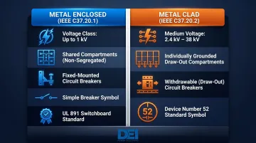
UL 891-certified switchboards fall under the metal enclosed classification. DEI Power manufactures these assemblies using fixed-mount molded case circuit breakers (MCCBs) in a shared enclosure. On an SLD, they appear as standard breaker symbols without the "52" device designation.
The SLD's Lifecycle Role
The SLD begins as a design concept, evolves through engineering reviews, becomes the basis for procurement and manufacturing specs, and then serves as the reference document during installation, commissioning, and maintenance. Manufacturers should supply complete SLD documentation with every switchgear order. Engineers and contractors use that documentation to verify that as-built equipment matches design intent — a critical step before energization.
Key SLD Symbols Used in Metal Enclosed Switchgear
In North America, the governing standard for SLD symbols is ANSI/IEEE 315-1975 (reaffirmed 1993, inactive-reserved since 2019). International diagrams follow IEC 60617. These two symbol sets differ significantly — most notably for circuit breakers, transformers, and protection devices. Always check which standard the SLD references in the title block before interpreting symbols.
Circuit Breakers and Fuses
Low-voltage circuit breakers (under 1,000V) appear as a diagonal line through the conductor path. Medium-voltage breakers incorporate ANSI device number 52 inside a square or circle symbol. Fixed-mount breakers in UL 891 switchboards typically lack the 52 designation, while draw-out breakers may include it.
Fuses use a separate rectangle symbol (ANSI) or a rectangle with a straight line through it (IEC). Fuses commonly appear in feeder circuits on metal enclosed switchgear.
Busbars and Conductors
The main horizontal or vertical line running through the SLD represents the main bus, the backbone of the switchgear lineup. Lines branching from it represent feeder conductors.
Bus ratings (ampacity and short-circuit withstand) must appear on or adjacent to the bus symbol. Per NEC 408.6, switchboards must carry a short-circuit current rating not less than the available fault current at the point of installation — verify this against your fault current study.
Current Transformers (CTs) and Potential Transformers (PTs)
CTs appear as a circle encircling the conductor; PTs/VTs use two linked circles indicating transformer winding. CTs step down current for metering and protective relays; PTs step down voltage.
Per IEEE C57.13-2016, CT designations on SLDs must include:
- Ratio (e.g., 3000:5A)
- Accuracy class (C for relaying, T for tested performance)
- Burden rating (e.g., C200 = 200V at 20× rated current)
C-class accuracy means 3% accuracy at rated current and 10% at 20 times rated current. Missing or incorrect CT data directly affects protective relay calibration — an error here can cause nuisance trips or, worse, missed fault detection.
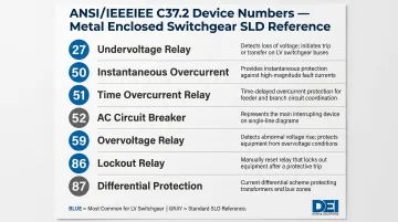
Protection Relay Device Numbers (ANSI C37.2)
Protection functions are identified by ANSI device numbers in circles (per IEEE C37.2-2022). These numbers tell you which protective function is active for each circuit.
Common Device Numbers on Metal Enclosed Switchgear SLDs:
| Device No. | Function | Application |
|---|---|---|
| 27 | Undervoltage Relay | Opens breaker when voltage drops below threshold |
| 50 | Instantaneous Overcurrent | Trips immediately on overcurrent (no delay) |
| 51 | Time Overcurrent | Trips with inverse time delay proportional to current |
| 52 | AC Circuit Breaker | MV draw-out breaker (less common on LV switchgear) |
| 59 | Overvoltage Relay | Opens breaker when voltage exceeds threshold |
| 86 | Lockout Relay | Hand-reset master trip device |
| 87 | Differential Protection | Trips on current difference between two points |
Low-voltage metal enclosed switchgear most commonly uses 27, 50, 51, 59, and 86. Device 87 may appear at the main bus level for larger installations.
Meters, Relays, and Miscellaneous Devices
Beyond protection devices, several auxiliary symbols appear on most switchgear SLDs:
- Power meters — watt-hour and demand types track energy consumption
- Ammeters and voltmeters — measurement devices for real-time monitoring
- Surge protective devices (SPDs) for lightning and transient suppression
- Control power transformers (CPTs) supplying 120V AC or 125V DC to control circuits
- Ground fault sensors positioned to detect faults before they escalate
Identifying these correctly is what separates a surface-level SLD read from one that's actually useful during commissioning or troubleshooting.
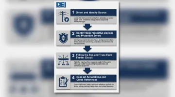
How to Read a Single-Line Diagram: Step-by-Step
Reading an SLD requires tracing power flow, verifying protection logic, and cross-referencing annotations to confirm equipment matches design intent — in that order.
Step 1: Orient Yourself — Identify the Source and Power Flow Direction
Locate the utility service entry point or generator at the top of the diagram. On metal enclosed switchgear, this is typically the incoming main breaker section. Confirm that the SLD includes:
- Utility service voltage (e.g., 480Y/277V, 208Y/120V)
- Available fault current (short-circuit kA rating)
- Whether the source is single-feed or dual-feed with a tie breaker
Check whether the diagram uses top-to-bottom (most common) or left-to-right power flow convention, as this affects how you trace feeder circuits.
Step 2: Identify the Main Protective Devices and Zones of Protection
Trace the main circuit breaker (labeled M1 or similar) and any upstream fuses or incoming disconnect. Note the breaker's:
- Frame rating (e.g., 1200AF)
- Trip rating (e.g., 1000AT)
- Interrupting capacity (e.g., 65 kAIC)
These must match the available fault current at the point of service. Per NEC 408.6, switchboards must have a short-circuit current rating not less than the available fault current, and this value must be field-marked on the enclosure.
Identify protection zones marked by CT boundaries and associated relay device numbers (50/51, 87, etc.). Each zone of protection — main, bus differential, feeder — should be delimited by CT placement on the SLD.
Step 3: Follow the Bus and Trace Each Feeder Circuit
Read the main bus rating (ampacity, e.g., 1200A) and follow each feeder circuit branching from the bus. Each feeder should show:
- Breaker rating (frame and trip)
- Load description or panel designation (e.g., "Panel A," "MCC-1")
- Conductor size or cable type (if noted)
- Overcurrent protection settings (e.g., LSIG trip unit parameters)
Check whether a bus tie breaker is shown for dual-bus or main-tie-main configurations. This indicates redundancy capability — common in data centers, healthcare facilities, and industrial lineups where uptime is critical.
Step 4: Read All Annotations, Notes, and Cross-References
Once you've traced the circuits, shift attention to the text. Annotations and schedules carry just as much engineering intent as the symbols themselves. Review:
- Enclosure type (NEMA rating: NEMA 1 indoor, NEMA 3R outdoor)
- Trip unit requirements (LSIG, LSIA, zone-selective interlocking)
- Metering accuracy class (for revenue metering vs. monitoring)
- CT ratios (must match relay calibration)
- Conductor types (copper vs. aluminum, temperature rating)
Missing or misread notes are the leading cause of field discrepancies and change orders. Cross-reference the SLD against the switchgear's equipment schedule. Every breaker shown on the diagram must correspond to a physical section in the lineup with matching ratings.
Key Annotations and Parameters to Check on a Metal Enclosed Switchgear SLD
Equipment ratings annotated on the SLD serve as the technical basis for code compliance, short-circuit withstand verification, and selective coordination. Every annotation must be accurate and traceable to the physical equipment.
Bus Ampacity and Bracing Rating
Verify:
- Bus ampacity (e.g., 1600A continuous)
- Short-circuit withstand rating (e.g., 65 kA RMS symmetrical)
Per UL 891, standard SCCR values include 5,000; 10,000; 14,000; 18,000; 22,000; 25,000; 30,000; 35,000; 42,000; 50,000; 65,000; 75,000; 85,000; 100,000; 125,000; 150,000; and 200,000 amperes. The SLD annotation must match the equipment nameplate.
Breaker Interrupting Rating vs. Available Fault Current
Each breaker's interrupting rating (kAIC) must exceed the available fault current at that point in the system. If a transformer is part of the lineup, verify transformer impedance (%Z) — it directly determines downstream fault current levels. Per Eaton's technical guidance, transformers have a ±7.5% impedance tolerance; use 0.925 × %Z for worst-case (highest fault current) calculations.
Voltage Annotations
Confirm the SLD clearly labels:
- Service voltage (e.g., 480V, 3-phase, 3-wire)
- Utilization voltage (e.g., 480Y/277V for lighting circuits)
- Control power voltage (e.g., 120V AC or 125V DC for relay/trip circuits)
Missing voltage labels are a common source of wiring errors during commissioning — and that same documentation gap creates problems when verifying UL listing compliance after field modifications.
UL 891 Certification and Field Modifications
For UL 891-certified metal enclosed switchgear — such as the switchboards manufactured by DEI Power — the SLD must align with the UL listing markings on the actual equipment. Per the UL Dead-Front Switchboard Marking Guide, "UL does not know what the effect of a modification may have on the safety of the switchboard...unless the field modification(s) have been specifically investigated by UL."
Busbars are not Listed for field tapping unless there are existing holes marked with the word "Tap." Any field modifications that deviate from the SLD can void the UL listing and create code compliance issues, making documentation accuracy non-negotiable.
Common Mistakes When Reading a Metal Enclosed Switchgear SLD
Confusing Symbol Standards
Using IEC 60617 interpretations on an ANSI/IEEE 315 diagram (or vice versa) leads to misidentified components, particularly for circuit breakers, transformers, and protection relay symbols. According to KTH Electric, the core difference is visual: IEC 60617 uses logical, rectangular "box" shapes, while ANSI uses pictorial shapes that mimic physical components. Always verify which standard the SLD references in the title block.
Ignoring ANSI Device Numbers and Protection Logic
Many readers focus on physical components and skip the relay function circles and their output connections (dashed trip lines). Failing to trace trip logic means you won't understand which conditions cause which breakers to open — critical for commissioning and fault response.
Zone-selective interlocking (ZSI), for instance, can reduce incident energy from 13.8 cal/cm² to 2.1 cal/cm² at 10 kA fault current. That reduction only happens if the ZSI connections shown on the SLD are properly commissioned in the field.
Treating the SLD as a Complete Wiring Document
The SLD shows system topology and single-line power flow, not actual wire-by-wire connections. Readers who try to use it as a wiring diagram will miss:
- Parallel conductors
- Control circuit details (auxiliary contacts, relay coils)
- Grounding configurations (only appear in multi-line schematics)
- Terminal designations and wire numbers
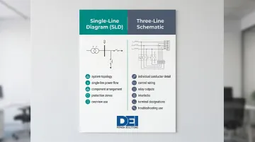
For detailed troubleshooting and wiring, you need the three-line (schematic) diagram and connection drawings — not just the SLD.
Frequently Asked Questions
What is metal enclosed switchgear?
Metal enclosed switchgear is an assembly of switching and protection devices housed within a grounded metal enclosure, used to control and distribute electrical power in commercial, industrial, and utility applications. Unlike metal clad switchgear, components may share a common enclosure separated only by insulated barriers. IEEE C37.20.1 governs the low-voltage metal-enclosed category.
What is the single-line diagram of a substation?
A substation SLD traces power flow from the high-voltage incoming supply through step-down transformers to distribution buses and outgoing feeders, showing all major components including circuit breakers, CTs, PTs, and fuses. It serves as the primary reference for utility coordination and power system studies.
What standard symbols are used in a single-line diagram?
North American SLDs use ANSI/IEEE 315-1975 symbols (now withdrawn); international diagrams follow IEC 60617. Both standards define symbols for breakers, transformers, CTs, PTs, fuses, buses, and protection relays. The applicable standard is always identified in the SLD title block.
What is the difference between a single-line diagram and a schematic diagram?
An SLD shows system-level power flow using one line to represent all three phases; a schematic (multi-line) diagram shows each individual conductor, control wiring, relay outputs, and interlocks in full detail. The SLD is the overview; the schematic is used for detailed troubleshooting and wiring.
What ANSI device numbers commonly appear on metal enclosed switchgear SLDs?
Common device numbers, as defined in ANSI/IEEE C37.2, include:
- 52 — Circuit breaker
- 50/51 — Instantaneous/time overcurrent
- 27 — Undervoltage
- 59 — Overvoltage
- 87 — Differential protection
- 86 — Lockout relay
How do I verify that an SLD matches the actual switchgear configuration?
Cross-reference the SLD against the equipment schedule and nameplate data, confirming that breaker frame sizes, CT ratios, bus ratings, and NEMA enclosure designations match what was manufactured and installed. Flag any discrepancies to the engineer of record before energization.