This guide explains what information you need to gather, how the quoting process flows from documentation review through final submittal, and what commonly goes wrong when teams try to quote MTM switchboards without providing manufacturers the right inputs. If you've ever faced a rejected submittal or had to restart lead times mid-project because a tie breaker was undersized or bus bracing was calculated for only one source, this article will help you avoid those outcomes.
Key Takeaways
- Main-Tie-Main switchboards feature two independent mains and a normally-open tie breaker, enabling redundant power switching for critical systems
- Accurate quotes require a single-line diagram, fault current from both sources, bus ampacity, tie breaker sizing, and interlock type
- Missing fault current data or interlock scheme details cause misquoted breaker ratings, wrong bus bracing, and rejected submittals
- UL 891 certification and NEC Article 110.26 working-space rules must be confirmed before finalizing any switchboard layout or quote
- Suppliers with in-house engineering catch specification gaps before they become change orders or delayed submittals
What Is a Main-Tie-Main Switchboard?
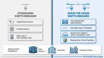
A Main-Tie-Main (MTM) switchboard is a low-voltage power distribution assembly featuring two independent incoming main breakers—each fed by a separate power source—and a normally-open tie breaker positioned between them. This configuration allows either source to supply the entire bus if the other fails, delivering the redundancy required in mission-critical facilities.
IEEE defines this arrangement as a "dual radial secondary selective system" designed to enhance both maintainability and operability. The tie breaker doesn't just provide an extra disconnect—it incorporates interlocking logic (mechanical, electrical, or Kirk Key) that prevents both mains and the tie from closing simultaneously, guarding against backfeed and unintended source paralleling.
How MTM differs from standard switchboards:
- Standard main-lug or main-breaker boards have one power source and zero redundancy
- MTM supports dual utility feeds, utility-plus-generator, or utility-plus-UPS scenarios
- Data centers, hospitals, and industrial plants use MTM specifically because downtime isn't acceptable
Interlock logic is where most MTM quotes go wrong. The tie breaker must coordinate with both main breakers and often integrates with automatic bus transfer schemes. Specifying the wrong interlock type—or leaving it undefined—leads directly to redesigns, extended lead times, and submittal rejections. Getting it right starts with understanding each specification decision covered in this guide.
Why Quoting Main Tie Switchboards Is More Complex Than Standard Switchboards
A standard switchboard quote requires one set of fault current data and one main breaker rating. An MTM quote requires fault current data from two independent sources—both of which affect bus bracing, breaker AIC (ampere interrupting capacity) ratings, and tie breaker selection. These values can differ significantly depending on whether your sources are utility-utility, utility-generator, or utility-UPS—and that gap directly determines how the assembly must be rated and coordinated.
What happens without correct MTM-specific inputs:
- Tie breakers get undersized relative to the mains, violating selective coordination under NEC 700.32
- Bus bracing gets specified for only one source's fault contribution, leaving the assembly unrated for the alternate source and violating NEC 110.10
- Interlock schemes are left undefined, forcing the manufacturer to default to a manual option that often doesn't match project specs requiring automatic bus transfer with relay control
These specification gaps aren't just quoting errors—they create compliance failures that surface during inspection or, worse, during a fault event.
Code-sensitive classification:
MTM configurations face additional scrutiny under NEC 230.71, which limits service disconnects. The 2020 NEC revision requires each service to have only one disconnecting means unless specific configurations under 230.71(B) are met.
If both sources are utility-derived, the MTM may be classified as a service entrance—changing labeling, grounding, and ground-fault protection (GFP) requirements.
Key NEC trigger: Service disconnects rated 1000A or more require GFP on solidly grounded wye services between 150V and 1000V to ground (typically 277/480V systems), per NEC 230.95.
What Information You Need to Get an Accurate Quote
Single-Line Diagram (SLD)
The SLD must show both source feeds, the main breakers, the tie breaker, and all outgoing feeders with their ampacity. Without this, the manufacturer cannot confirm bus layout, section count, or breaker placement.
What to include:
- Both incoming power sources clearly labeled (utility 1, utility 2, generator, UPS, etc.)
- Main breaker sizes and ratings
- Tie breaker position in the lineup (center vs. end section)
- All outgoing feeder circuits with design current
If you're early in design, submit what you have. DEI Power's in-house engineering team in Ontario, California can review a draft SLD and provide configuration guidance to resolve discrepancies before manufacturing begins.
Fault Current from Both Sources
Both sources must be evaluated independently, and bus bracing must be rated to the higher of the two available fault currents. The tie breaker AIC rating must also be verified for closed-transition or momentary paralleling scenarios if your control scheme allows it.
Critical details:
- Provide fault current in kiloamperes (kA) for each source
- Data comes from the utility company or your project's engineer of record
- If you're integrating a generator or UPS as the secondary source, confirm its contribution during a closed-transition transfer
NEC 110.9 requires equipment intended to interrupt fault-level current to carry an interrupting rating no less than the available current at the line terminals. Undersized bus bracing or breaker AIC ratings violate this requirement, which can result in inspection failure or severe equipment damage during a fault.
Main Bus Ampacity and Tie Breaker Sizing
The two main breakers are typically equal in frame size (e.g., 2000A, 3000A, 4000A). The tie breaker is usually the same frame size as the mains—but this is a design assumption that must be confirmed, not defaulted.
Why this matters:
- Any deviation (e.g., a smaller tie breaker) must be justified by engineering
- Tie breaker sizing affects selective coordination and arc flash calculations
- Main bus ampacity determines physical enclosure dimensions and section count
Interlock Type and Control Scheme
Three common interlock options:
| Interlock Type | Description | Impact on Cost & Lead Time |
|---|---|---|
| Mechanical (Kirk Key) | Physical key transfer prevents simultaneous closure | Simplest, fastest to build |
| Electrical (Relay-based) | Automatic bus transfer with control logic | Requires additional wiring, relay package, and controls section; longer lead time |
| Manual | Operator manually opens/closes breakers per procedure | Lowest cost, but requires training and documented procedures |
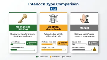
Automatic schemes require additional control wiring and may need a separate controls section or automatic transfer switch (ATS) relay package. If the interlock type is left undefined, the manufacturer will assume manual operation. That assumption can require a full redesign if your spec calls for automatic bus transfer.
Feeder Schedule and Load Requirements
The feeder schedule directly determines how many breaker sections are needed and how the enclosure is configured. Provide a row-by-row list of all outgoing feeders, including:
- Design current for each circuit
- Circuit quantity and load type
- Special loads (motors, emergency circuits, fire pump)
This drives the number of breaker sections, required separation between load types, and overall enclosure size.
NEC 700.10(B)(5) requirement: Emergency circuits must be housed in separate vertical switchboard sections from all other loads. If your MTM board serves emergency systems, this adds sections and affects footprint and cost.
Physical and Environmental Constraints
Required details:
- Enclosure footprint and available room dimensions
- Cable entry direction (top or bottom)
- NEMA rating for installation environment:
- NEMA 1: Standard indoor, controlled environments
- NEMA 3R: Outdoor, weather-resistant (rain, sleet, snow)
- Whether the board is service entrance rated
- NEC 110.26 working space clearances:
- Minimum 3 feet depth for 0-150V systems
- Minimum 3.5 feet (Condition 2) or 4 feet (Condition 3) for 151-600V systems
- Minimum width of 30 inches or equipment width, whichever is greater
- Minimum height of 6.5 feet (78 inches)
How the Quoting Process Works: Step by Step
An MTM switchboard quote moves through three distinct stages: document collection and configuration validation, engineering review and BOM generation, then a formal written quote with lead time and compliance callouts. Rushing the first stage causes most quote inaccuracies.
Step 1: Compile and Submit Documentation
Submit your single-line diagram, fault current data, load schedule, and physical/environmental constraints in a single organized package. Submitting these together—rather than piecemeal—significantly reduces quote turnaround.
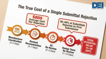
Why this matters: 30-40% of construction submittals are rejected on first submission, costing an average of $805 per rejection and adding 2-3 weeks to the schedule. A single rejection cycle typically includes:
- Manufacturer coordination: 3-5 days
- Revised documentation: 3-7 days
- GC re-review: 2-3 days
- Design team re-review: 7-14 days
Incomplete submittals result in a budget-range estimate rather than a firm quote.
Step 2: Engineering Review and Configuration Validation
Once the full document package is in hand, the engineering review begins. The manufacturer's engineering team reviews the SLD to:
- Confirm bus bracing matches the higher of the two fault current values
- Verify tie breaker and main breaker sizing are coordinated
- Flag any interlock conflicts or NEC compliance issues
- Confirm UL 891 listing requirements
UL 891 scope: Covers dead-front distribution switchboards rated at 1000V or less with minimum bus ratings of 800A and maximum ratings up to 6000A. This is the recognized standard for low-voltage switchboards in North America.
DEI Power's in-house engineering team provides configuration guidance at this stage to resolve mismatches before manufacturing begins — catching problems at the design stage, not on the jobsite.
Step 3: Quote Delivery and Scope Lock
A complete, accurate MTM quote should include:
- Itemized BOM with breaker part numbers and ratings
- Bus ampacity, bracing rating (in kA), and enclosure dimensions (W × D × H)
- Interlock scheme description (mechanical, electrical, or manual)
- UL 891 listing confirmation
- Lead time estimate
- Any assumptions that remain subject to confirmation (e.g., final fault current values)
Open assumptions are called out explicitly in the quote. Any changes after scope lock may restart the lead time clock — which matters considerably on compressed construction schedules.
Key Factors That Affect Pricing and Lead Time
Configuration Complexity
A manually interlocked MTM board with a Kirk Key scheme is simpler and faster to build than an electrically interlocked board with automatic bus transfer logic and a relay control section. While specific cost differentials vary by project, automatic transfer schemes add:
- Motorized breaker operators
- Control relays and logic boards
- Additional wiring and terminations
- Testing and commissioning time
Custom vs. Standard Section Sizing
MTM switchboards are typically custom-built because section count, bus layout, and interlock wiring are project-specific. Manufacturers with in-house fabrication—like DEI Power's 50,000 sq. ft. Ontario, California facility—can build to spec faster than those relying on third-party assembly.
Industry benchmark: A manufacturer case study documented a conventional 30-week manufacturing cycle for custom switchboard lineups. Expedited builds achieved 9-week delivery by moving to two-shift operations, using overtime, and having the customer supply their own circuit breakers.
That comparison illustrates the value of vertical integration. DEI Power's in-house manufacturing typically delivers custom MTM builds in 4-6 weeks from scope lock, with standard delivery in 3-5 business days after production.
Component Availability
Main breakers in large frame sizes (2000A–4000A) and tie breaker interlocking hardware can have extended lead times. The Sparkstone case study revealed that even when enclosure fabrication was compressed to 9 weeks, the customer still had to supply their own circuit breakers to meet the timeline.
Confirm component availability early in the quote process and order critical items as soon as scope is locked. Breaker lead times—not enclosure fabrication—are often the bigger bottleneck.
Common Mistakes When Quoting Main Tie Switchboards
These three mistakes show up repeatedly in quote requests — each one capable of triggering redesigns, cost surprises, or field failures. Catching them early keeps your project on schedule.
Treating the Tie Breaker as a Generic Third Breaker
Many teams assume the tie breaker can be any breaker of the same amperage as the mains, without accounting for its specific role in the bus transfer scheme. The tie breaker must:
- Be sized and rated to handle the combined bus fault current contribution during a closed-transition transfer
- Have its interlock logic validated against the control scheme
- Meet selective coordination requirements with both main breakers
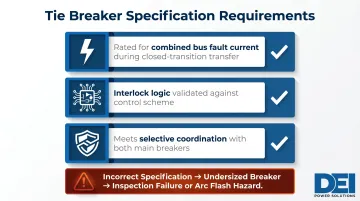
Failing to specify this correctly results in an undersized breaker that fails inspection or creates arc flash hazards.
Omitting Fault Current from One of the Two Sources
Teams often provide fault current for the primary utility source but skip fault current calculations for the secondary source — whether that's a generator, second utility feed, or UPS. This leaves:
- Bus bracing unverified for the alternate source's contribution
- Tie breaker AIC rating unconfirmed for the secondary source
- Equipment potentially undersized for the actual installation conditions
Arc flash impact: IEEE 1584-2018 calculates arc flash incident energy based on available fault current and enclosure dimensions. Undersized bus bracing directly increases incident energy and hazard severity, affecting PPE requirements and worker safety.
Leaving Interlock Type Undefined
Interlock selection connects directly to both cost and lead time — yet it's frequently left blank on quote requests. Without a specified scheme, manufacturers default to the simplest manual option. If your spec calls for automatic bus transfer with relay logic, that gap can:
- Require a full redesign and restart of the lead time clock
- Add unplanned costs for motorized operators and control sections
- Delay project schedules by 2-3 weeks or more
Include mechanical, electrical, or manual interlock requirements in your initial quote request — along with any automatic transfer control requirements — to avoid these delays.
Frequently Asked Questions
What is a main-tie-main switchboard configuration?
A Main-Tie-Main (MTM) switchboard features two independent main breakers (each served by a separate power source) and a normally-open tie breaker between them. This allows either source to feed the entire bus if the other fails, providing the redundancy required in data centers, hospitals, and critical industrial facilities.
What are the main parts of a switchboard?
Key components include:
- Main busbars — carry current through the assembly
- Main circuit breakers — incoming overcurrent protection
- Feeder breakers — outgoing distribution
- Neutral and ground buses
- Metering components and enclosure structure
An MTM board adds a tie breaker section and interlock logic to this standard layout.
What is the clearance for a switchboard?
NEC Article 110.26 requires a minimum of 3 feet of working space in front of switchboards for 0-150V systems, and 3.5 to 4 feet for 151-600V systems depending on equipment configuration. Switchboard room dimensions must be confirmed before finalizing enclosure layout in the quote.
What is the standard size of a switchboard module?
Switchboard sections are typically 20-24 inches wide and 90 inches tall, with depth varying by bus ampacity and breaker type. MTM configurations require three or more sections (one per main, one for the tie, plus feeder sections), making total lineup width a critical space planning input.
What documents do I need to quote a main tie switchboard?
You need three essentials: a single-line diagram showing the MTM configuration, fault current data (in kA) from both power sources, and a feeder load schedule. Without all three, only a budgetary estimate is possible.
How long does it take to build a custom main tie switchboard?
DEI Power typically completes custom MTM builds in 4-6 weeks from its 50,000 sq. ft. Ontario facility, with delivery in 3-5 business days after production. In-house manufacturing eliminates third-party assembly delays that stretch timelines at other suppliers.
Ready to quote your Main-Tie-Main switchboard? Contact DEI Power at (866) 773-8050 or email sales@deipower.com for engineering support and a detailed quote. With in-house manufacturing, UL 891 certification, and BABA-compliant construction, DEI Power delivers custom MTM switchboards with accurate configurations, code-compliant documentation, and lead times built around your schedule.