Main-Tie-Main (MTM) switchgear directly addresses this risk. Also called a secondary-selective system, MTM is the most widely adopted configuration for achieving redundant low-voltage power distribution. It eliminates the single point of failure by providing two independent power sources, each capable of carrying the full facility load. This guide covers what MTM is, how it operates during normal and fault conditions, how to size transformers and breakers correctly, configuration variants like Main-Tie-Tie-Main (MTTM), and where MTM is most justified — from hyperscale data centers to healthcare facilities and industrial plants.
Key Takeaways
- MTM uses two independent sources, two main breakers, and a normally-open tie breaker connecting two bus sections
- Each transformer must be rated for 100% of the combined load, not just its normal 50% share
- When one source fails, the tie breaker closes — automatically or manually — so one transformer carries the full load
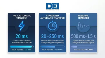
- Transfer times range from 20 milliseconds (fast automatic) to 1.5 seconds (residual transfer) based on the control scheme
- Common applications include data centers, hospitals, industrial facilities, and utility substations
What Is Main-Tie-Main Switchgear Configuration?
Main-Tie-Main (MTM) is a secondary-selective power distribution system consisting of two independent power sources, each connected to a separate bus section through its own main circuit breaker, with a normally-open tie breaker connecting the two buses. The name reflects the physical breaker arrangement: Main breaker 1 (CB1), Tie breaker, Main breaker 2 (CB2).
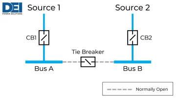
The fundamental goal is to eliminate single points of failure in the distribution system. If one transformer, power source, or main breaker fails, the tie breaker closes and the remaining source continues to power all connected loads without sustained outage.
This topology applies at both low-voltage (secondary) and medium-voltage levels, though UL 891-certified low-voltage switchboards are the most common implementation in commercial and industrial facilities.
The NIH Office of Research Facilities summarizes the operational value directly:
"MTM provides enhanced load recovery following faults/outage and provides operational flexibility. Maintenance of upstream transformer, cable, and switchgear bus doesn't require a shutdown since the affected main can be taken out of service while the other main and tie breaker maintain continuity of power to all the loads."
Several codes and standards govern MTM design and installation:
- UL 891: Covers dead-front switchboards rated up to 1,000V for commercial and industrial use
- NEC Article 408: Governs installation requirements for switchboards and panelboards
- IEEE C57.91: Provides transformer loading guidelines for secondary-selective applications
- NEC Articles 230 and 240: Cover service entrance equipment and overcurrent protection
How Main-Tie-Main Works: Normal Operation and Fault Transfer
Normal Operating State
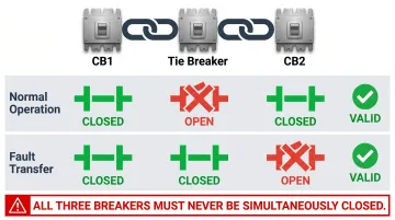
During normal operation, both main breakers (CB1 and CB2) remain closed while the tie breaker stays normally open (NO). This configuration splits the facility into two independent bus sections:
- Bus A is energized by Source 1 through CB1
- Bus B is energized by Source 2 through CB2
- Each bus section carries approximately 50% of the total facility load
Operating at 50% capacity during normal conditions is intentional, not wasteful. This headroom preserves each transformer's ability to absorb 100% of the load when the tie closes during a fault or maintenance scenario.
As IEEE standards confirm, "loads are fed from redundant transformers normally loaded to less than 50% of their kilovoltampere rating" — ensuring the system can carry full load on a single source without overloading during a contingency.
Fault Transfer Sequence
When one source fails, the system executes an open-transition transfer sequence:
- Fault detection: Protective relays sense loss of voltage or overcurrent on Source 2
- Main breaker trips: CB2 opens (automatically or manually), de-energizing Bus B
- Tie breaker closes: The normally-open tie breaker closes, connecting Bus B to Bus A
- Load restoration: All loads now draw power through Source 1 via Bus A
The transfer time varies by control scheme. According to SEL's 2024 technical paper, transfer speeds include:
| Transfer Type | Timing | Description |
|---|---|---|
| Fast automatic | 20 ms | Communications-assisted, initiated by upstream breaker status |
| Staggered automatic | 20–250 ms | Delayed to prevent simultaneous inrush on shared transformers |
| Residual transfer | 500 ms – 1.5 s | Open-transition; waits for voltage decay before closing alternate source |
Return to normal: Once Source 2 is restored and verified, CB2 recloses and the tie breaker reopens, returning the system to standard split-bus operation.
Maintenance Use Case
Beyond fault response, MTM handles planned maintenance the same way — without taking operations offline. The same transfer logic that responds to faults can be initiated deliberately by operators:
- Open CB2 to isolate Source 2
- Close the tie breaker, transferring Bus B loads to Source 1
- Perform upstream work on Source 2, its transformer, or associated equipment
- Restore the system by closing CB2 and reopening the tie breaker
Radial systems don't offer this option — any upstream maintenance means a full shutdown. For hospitals, data centers, and manufacturing plants running continuous operations, that distinction directly affects uptime.
Key Components of a Main-Tie-Main Switchgear Lineup
Main Circuit Breakers (CB1 and CB2)
The two main circuit breakers serve as primary protection and isolation devices for each source. Each main breaker must be rated for:
- Continuous current capacity matching the full load of its bus section
- Interrupt rating sufficient for the available fault current from the source
- Short-circuit withstand coordinated with upstream transformer and downstream distribution equipment
Breaker ratings must align with the upstream transformer capacity and the system's protection coordination study. Since each transformer in an MTM system is sized for 100% of the total load, the main breaker protecting it must also handle that full capacity.
Tie Breaker
The tie breaker sits between the two bus sections and remains normally open during standard operation. It closes only when directed by an automatic transfer scheme or manual command. Critical design requirements include:
- Three-way interlock requirement: Must be interlocked (mechanically, electrically, or both) to prevent simultaneous closure with CB1 and CB2, which would unintentionally parallel two sources
- Load capacity: Must be rated to carry 100% of the combined facility load
- Control integration: Must interface with protective relays and automatic bus transfer controllers
Kirk Key mechanical interlocks are the most common method for preventing paralleling: "All main breakers shall be equipped with Kirk Key interlocks coordinated with Kirk Key interlocks on all tie breakers to prevent paralleling of the incoming lines."
Bus Sections and Busbars
Each bus section (Bus A and Bus B) is a separate copper or aluminum busbar assembly within the switchgear lineup. A critical design rule: each busbar must be sized to carry 100% of the total load, not just the 50% it normally serves. When the tie closes, one bus must conduct the entire facility's current without overheating or voltage drop.
Protective Relays and Controls
The busbars and breakers handle the physical power path — but the protective relays and automatic bus transfer (ABT) controllers are what coordinate them. These systems detect source failures and execute transfer sequences without operator intervention. Key relay functions include:
- Undervoltage sensing: Detects loss of source voltage
- Overcurrent protection: Trips breakers during fault conditions
- Loss-of-source detection: Monitors source availability continuously
- Antiparallel logic: Prevents unintended paralleling of sources
UL 891-certified switchgear lineups can be configured with integrated relay panels, metering, and interlocking schemes tailored to project-specific control logic. DEI Power builds these assemblies to order from their Ontario, California facility, with each lineup engineered to match the transfer sequence and protection requirements of the application.
Main-Tie-Main Configuration Variants
Main-Tie-Tie-Main (MTTM)
MTTM extends the standard MTM topology with two tie breakers and physical separation between bus sections. The configuration places each tie breaker in a separate switchgear assembly, allowing the two lineups to be located in different rooms or areas.
Key advantages:
- Allows de-energized maintenance: with both ties open, technicians can work on either lineup without exposure to live equipment
- Limits fault propagation: physical separation prevents a failure in one lineup from damaging the other
- Cuts short-circuit duty: during maintenance, each bus sees only one source's fault current
As one electrical engineer noted on Mike Holt's forums, "In normal MTM one side of the Tie device or compartment is always energized, making maintenance an 'energized task'. With a MTTM there is only one short circuit current available when both Ties are opened."
Main-Main (No Tie Breaker)
The Main-Main arrangement eliminates the tie breaker entirely, permanently connecting both buses. In this configuration:
- One source normally carries the full load
- The other source remains on standby
- Transfer occurs by opening the loaded main and closing the standby main
This functions similarly to an automatic transfer switch (ATS) but within a switchgear lineup. Main-Main reduces equipment cost compared to MTM, though both sources cannot simultaneously share load — so operational flexibility is more limited.
Closed-Bus (Normally Closed Tie) Operation
Some installations run the tie breaker in a normally-closed position, effectively paralleling the two sources during normal operation. This eliminates any momentary outage during source transfer (no "dead zone"), but it introduces meaningful protection complexity:
- Doubled fault current: Schneider Electric warns that "available fault current at the secondary switchgear can be doubled" with closed-tie operation
- Directional overcurrent (67) relays required: IEEE Houston Section guidance confirms these relays are mandatory to prevent miscoordination
- Protection grading delay: Adds approximately 300 ms to main breaker protection operation time
- Synchronization requirements: Sources must be synchronized if they are separate utility feeds or generators
Closed-bus operation is best suited for facilities where zero-interruption transfer justifies the added relay engineering — typically large industrial plants or critical process environments, not standard commercial builds.
Main-Tie-Main Design Considerations
Transformer Sizing
Critical rule: Each transformer feeding an MTM system must be rated to carry 100% of the combined load, not just its normal 50% share. This is the single most important sizing requirement in MTM systems.
Schneider Electric's design guide states it plainly: "The loss of transformer means the other transformer and its associated secondary main circuit must carry the entire load. Consider this in sizing the transformer and secondary switchgear for the effectiveness of this type of system."
Practical example:
- Normal load per bus: 1,000 kVA (total facility load: 2,000 kVA)
- Required transformer rating: Each transformer must be rated for at least 2,000 kVA
- Incorrect sizing: Installing two 1,250 kVA transformers (only 25% oversize) means a single transformer cannot handle the full 2,000 kVA load during contingency without risk of overload or damage
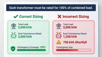
Cost implication: Larger transformers increase capital cost, but undersizing defeats the entire purpose of the MTM system. Undersizing risks transformer damage, overload tripping, or forced load shedding at exactly the moment the MTM topology is supposed to protect operations.
IEEE C57.91 provides loading guidelines for transformers in secondary-selective applications, addressing accelerated insulation aging when a single transformer carries full load during contingency.
Interlock Scheme
A proper interlock scheme ensures that one of the three breakers (CB1, Tie, CB2) is always open, preventing unintentional paralleling of two independent sources — a condition that can increase available fault current beyond equipment ratings and cause equipment damage.
Types of interlocks:
Mechanical (Kirk Key):
- Physical key-lock system that mechanically prevents simultaneous closure
- Key cannot be removed unless breaker is in the correct position
- Most reliable method, requires no electrical power to function
Electrical:
- Control logic and relay-based interlocks
- Prevent closing commands from being executed if another breaker is already closed
- SEL's antiparallel logic (described in their 2024 technical paper) serves as an electrical interlock: if all three breakers are detected closed, the tie breaker trips; if the tie fails to trip, the main breaker that just closed is tripped
Load Balancing
Distribute loads evenly across Bus A and Bus B during design. Unbalanced loading means one transformer will be heavily loaded when the tie closes, increasing the risk of overload or requiring derating adjustments.
Design strategy:
- Aim for 45-55% load split between buses during normal operation
- Group loads by criticality and operational profile
- Review load distribution during commissioning and adjust feeder connections as needed
Alternative approach — Load shedding:
For systems where oversizing transformers to 100% redundancy is too costly, a selective load-shedding scheme can drop non-critical loads upon tie closure. SEL case studies at wastewater treatment plants show these systems execute shed commands in 25-30 milliseconds from contingency detection.
Loads are organized into priority groups (typically 3-10 levels), with lowest-priority loads shed first — HVAC, lighting, non-essential processes. This allows smaller transformers and reduces system cost, but requires careful engineering to ensure critical loads are never shed unintentionally.
Code and Standards Compliance
MTM switchgear lineups for low-voltage applications must comply with:
- UL 891: Standard for dead-front switchboards rated up to 1,000V
- NEC Article 408: Switchboards, switchgear, and panelboards installation requirements
- NEC Article 230: Service entrance equipment requirements
- NEC Article 240: Overcurrent protection requirements
Equipment must be properly labeled indicating:
- Main breaker ratings and interrupt capacity
- Bus voltage and ampacity
- Source identification for each main breaker
- Interlock scheme operation and warning labels
DEI Power's UL 891-certified MTM switchgear lineups ship with full NEC compliance documentation — including service equipment labeling, overcurrent protection schedules, and interlock scheme descriptions — to support submittal packages and field inspections.
Where Main-Tie-Main Switchgear Is Used
MTM is most justified when the operational or financial cost of a power outage exceeds the additional investment in redundant sources, larger transformers, and tie breaker switchgear. Primary applications include:
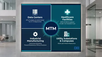
Data Centers and Colocation Facilities
Uptime Institute reports that 44% of major data center outages stem from power-related failures. Of those significant outages, 54% cost more than $100,000 and 16% exceed $1 million. Tier III and Tier IV data centers require redundant distribution paths and physically isolated systems — both align with MTM and MTTM topologies.
Healthcare Facilities
Hospitals lose an average of $7,500 per minute during downtime. For medium-sized facilities, that adds up to roughly $1.7 million per hour.
NFPA 99 defines the Essential Electrical System (EES), which requires redundant power distribution infrastructure for life-safety and critical care loads — making MTM a natural fit for hospital power systems.
Industrial Manufacturing and Processing
Continuous manufacturing operations — chemical processing, semiconductor fabrication, food processing — cannot tolerate production interruptions. MTM systems allow planned maintenance without shutdown and provide automatic transfer during source failures.
SEL case studies at LNG facilities and wastewater treatment plants confirm that main-tie-main configurations with automatic transfer schemes are standard in these environments.
Utility Substations and Commercial Campuses
These two segments share a common driver: serving multiple critical loads from a single distribution infrastructure.
- Utility substations serving critical infrastructure or large commercial loads use MTM at medium-voltage and low-voltage levels to maintain continuous service during equipment maintenance or source failures
- Large corporate campuses, research facilities, and universities with server rooms, laboratories, and emergency systems justify MTM investment to avoid operational disruption and protect business continuity
Frequently Asked Questions
What is a main tie main switchgear?
Main-Tie-Main switchgear is a redundant power distribution configuration consisting of two independent sources, each connected to a separate bus section through its own main breaker, with a normally-open tie breaker connecting the two buses. When one source fails, the tie breaker closes so the remaining source carries the full load without sustained outage.
What is the purpose of a tie breaker in switchgear?
The tie breaker serves as the interconnection point between two bus sections. It stays open during normal operation to keep sources independent, and closes automatically or manually when one source fails. This allows the remaining source to energize both buses without interrupting power to critical loads.
What are MCC and MCB?
An MCC (Motor Control Center) is a switchgear assembly used to control and protect motor loads from a centralized panel. An MCB (Miniature Circuit Breaker) is a small overcurrent protection device used in lower-current branch circuits. Both are commonly fed downstream of Main-Tie-Main switchgear but are distinct from the MTM lineup itself.
What is the difference between Main-Tie-Main and Main-Main configuration?
In MTM, the tie breaker is normally open and each source independently serves its bus under normal conditions. In Main-Main, the tie is normally closed and the two buses are permanently connected, meaning one source carries the full load while the other acts as standby, functioning more like a hot-standby arrangement.
How are transformers sized in a Main-Tie-Main system?
Each transformer must be rated to carry 100% of the total combined load. When one source fails and the tie closes, the remaining transformer must supply both bus sections simultaneously without overloading.
When should a Main-Tie-Main configuration be used over a simpler single-source topology?
MTM makes sense when downtime costs exceed $100,000 per incident or when life-safety systems require continuous power — data centers, hospitals, and continuous manufacturing operations are the most common candidates. The configuration requires redundant sources, larger transformers, and more complex switchgear, so the budget must support that premium.