Introduction
800 amp service installation is among the most technically demanding electrical projects in commercial and industrial construction. It requires licensed electricians, utility coordination, engineered equipment, and full NEC compliance.
The stakes at this ampacity are not theoretical. Loose connections at 800A generate enough heat to ignite insulation, and arc-flash hazards at this service size can cause fatalities, destroy equipment, and shut down entire projects.
This work is performed exclusively by licensed electrical contractors with commercial/industrial experience, working alongside utility engineers and AHJ (Authority Having Jurisdiction) inspectors. Most jurisdictions require engineer-stamped drawings at this service size, and utility interconnection involves formal approval processes that only licensed professionals can navigate.
This guide walks through the full 800A installation process — from NEC code requirements and pre-installation planning to sequencing, common failure points, and the best practices that keep commercial and industrial projects on schedule.
Key Takeaways
- 800A service requires licensed installation, utility approval, and compliance with multiple NEC articles (230, 240, 310, 408, 250)
- Conductor sizing depends on run length, conduit type, temperature rating, and voltage — use NEC Article 310 tables to confirm
- Complete load calculations, site readiness, and utility coordination before any physical work begins
- Switchboards must be UL-listed and rated for both service ampacity and available fault current
- AHJ inspection and utility sign-off are required before energization
NEC Code Requirements for 800 Amp Service
800A service is governed by multiple NEC articles simultaneously. Ignoring any one creates code violations that will fail inspection. This section focuses on the key articles and what they require at this ampacity.
Service Entrance: NEC Article 230
Article 230 governs how service conductors enter a building, covering service drop or lateral requirements, conductor sizing, clearances, and the requirement for a single main disconnecting means. At 800A, the main disconnect is typically a main breaker within a switchboard or a standalone service disconnect enclosure.
The 2020 and 2023 NEC editions permit a maximum of six service disconnecting means per service. However, if two to six disconnects are used, they must be in separate enclosures, separate vertical switchboard sections with barriers, or separate switchgear compartments. The NEC implemented this requirement to reduce arc-flash exposure hazards by eliminating the traditional main-lug-only "Rule of Six" panelboard configuration.
Overcurrent Protection: NEC Article 240
Overcurrent protection at 800A must protect conductors, stay within equipment ratings, and coordinate across the full distribution system. Main breakers must be listed and properly rated; fused disconnects are common in industrial applications.
800A is a standard overcurrent device rating per NEC Table 240.6(A). A critical threshold exists here: for overcurrent devices rated 800A or less, the next higher standard overcurrent device rating is permitted above the ampacity of the conductors being protected (NEC 240.4(B)). Above 800A, conductor ampacity must equal or exceed the device rating. In practical terms, this means conductor sizing for an 800A service has more flexibility than anything above it — a distinction that directly affects material costs and installation feasibility.
Conductor Ampacity: NEC Article 310
Article 310 tables govern conductor sizing. At 800A, parallel conductor runs (multiple conductors per phase) are typically required since single conductors that large become impractical to install.
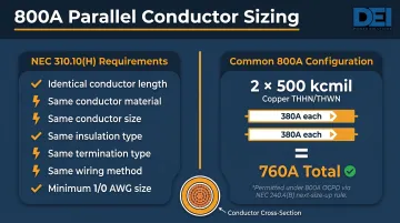
NEC 310.10(H) mandates that parallel sets use:
- Identical conductor length
- Same conductor material (all copper or all aluminum)
- Same size in circular mil area
- Same insulation type
- Same termination method
- Same wiring method (e.g., all in rigid metal conduit)
- Minimum conductor size of 1/0 AWG
For an 800A service, two parallel sets of 500 kcmil copper conductors are common. Per NEC Table 310.16, 500 kcmil copper THHN/THWN has an ampacity of 380A at 75°C. Two parallel sets yield 760A total ampacity, which is permissible with an 800A overcurrent device under the NEC 240.4(B) "next-size-up" rule.
Switchboards and Panelboards: NEC Article 408
Article 408 governs the construction, marking, and installation of switchboards. At 800A, a switchboard (rather than a panelboard) is typically the right equipment type.
- Switchboard: Large single panel accessible from front and rear; not installed in cabinets
- Panelboard: Panel units in a cabinet, accessible only from the front
All equipment must carry UL 891 listing for switchboards, include the "Suitable for Use as Service Equipment" (SUSE) marking, and be rated for the available fault current (AIC rating) at the point of installation per NEC 110.9.
Grounding and Bonding: NEC Article 250
At 800A, grounding requirements scale up considerably from residential standards. Article 250 mandates a properly sized grounding electrode conductor (GEC), main bonding jumper, and equipment grounding conductors throughout the system.
Per NEC Table 250.66, for an 800A service using two parallel sets of 500 kcmil copper (equivalent to 1000 kcmil total), the GEC size is determined by the largest service conductor. For 600-1100 kcmil copper, the minimum GEC is 2/0 AWG copper. If larger conductors are used (over 1100 kcmil), a 3/0 AWG copper GEC is required.
Prerequisites, Equipment, and Site Readiness
800A service installation cannot begin without completing a defined set of planning prerequisites. Rushing this phase is the most common cause of costly rework, permit failures, and project delays.
Utility Coordination and Permits
The local utility (POCO) must approve the service design before any work begins. This includes submitting single-line diagrams, load calculations, and metering configurations for utility review. Permits from the AHJ must also be obtained. Some jurisdictions require plan review before permit issuance for services above 400A.
At 800A, current transformer (CT) metering is required since self-contained meters are typically rated for a maximum of approximately 320A. Standard CT configurations use ratios such as 800:5, stepping measured current down to a range the revenue meter can read.
Load Calculations and Service Sizing Justification
The engineer of record must perform an NEC Article 220 load calculation to justify the 800A service size. This ensures code compliance and prevents unnecessary oversizing, which drives up both equipment and utility costs.
Demand load calculations consider:
- General lighting (per Table 220.12 VA/sq-ft by occupancy type)
- Receptacle outlets (180 VA per single/multiple receptacle on one yoke)
- Motor loads (per Article 430 full-load current tables)
- Fixed appliances and HVAC (using non-coincident load rule per 220.60)
- Continuous loads calculated at 125% for sizing overcurrent protection and conductors
Site Readiness and Physical Requirements
Physical prerequisites include:
- Adequate space for the switchboard/metering section
- Verification of utility clearance and NEC working space per Article 110.26
- Structural support for heavy equipment (800A switchboards are large and heavy)
- Conduit routing paths
- Adequate ventilation or environmental conditioning if equipment is installed indoors
NEC 110.26 requires minimum working space clearances for equipment operating at 151-600V to ground:
| Condition | Description | Minimum Depth |
|---|---|---|
| Condition 1 | Exposed live parts on one side, no live/grounded parts opposite | 3 ft (900 mm) |
| Condition 2 | Exposed live parts on one side, grounded parts opposite | 3.5 ft (1.1 m) |
| Condition 3 | Exposed live parts on both sides | 4 ft (1.2 m) |
Additional requirements: minimum width of 30 inches (762 mm), minimum headroom of 6.5 ft (2.0 m), and equipment doors must open to at least 90 degrees.
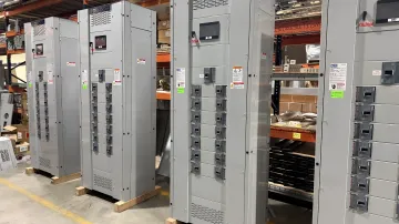
Switchgear and Switchboard Selection
The main switchboard drives every downstream distribution decision in an 800A service. It must be:
- Rated for the full service ampacity
- Carry an appropriate AIC rating for the fault current available at the site
- UL-listed (e.g., UL 891 for switchboards)
Wrong voltage class, insufficient AIC rating, or incorrect bus configuration each create unsafe conditions that will not pass inspection. Getting this selection right before procurement saves significant rework downstream.
DEI Power's UL 891-certified switchboards are built for commercial and industrial service at this scale. Configurations are tailored to project-specific voltage (120/240V, 208Y/120V, 480V, 480Y/277V), layout, and load requirements.
Available in NEMA 1 (indoor) or NEMA 3R (outdoor weather-resistant) enclosures, each unit uses genuine Siemens components with main breaker configurations sized to the available fault current. As an approved Siemens OEM, DEI Power provides detailed submittal documentation to support AHJ plan review and inspection.
Conductor Sizing and Conduit Planning
Conductor sizing for 800A must account for:
- Run length (voltage drop calculations)
- Conduit type (PVC vs. rigid metal conduit)
- Conductor temperature rating (75°C or 90°C)
- Whether parallel runs are being used
- Terminal temperature limits per NEC 110.14(C) — ampacity is typically capped at 75°C unless terminals are listed for 90°C
Conduit fill calculations (NEC Chapter 9) must be completed before conduit is installed. Switching conduit type mid-run often forces conductor resizing, so locking in the conduit specification early avoids costly field changes.
How to Install 800 Amp Service: Step-by-Step
This installation follows a defined sequence. Setting equipment before utility approval, or pulling wire before conduit inspection, creates rework — and can void equipment warranties or cause failed inspections. Follow the steps below in order.
Step 1: Establish the Service Point and Meter Base
Installation begins at the utility demarcation point: the meter base or utility-side metering section. The meter base must be utility-approved in terms of form factor, jaw configuration, and CT metering setup. At 800A, CT metering is standard since the conductors are too large for self-contained meters.
The utility typically sets the meter itself — the contractor installs the base and metering enclosure only.
Step 2: Install Service Entrance Conduit and Pull Service Conductors
Service entrance conduit must be installed per the approved design, maintaining:
- Required separation
- Weatherproofing at penetrations
- Correct conduit type
Service conductors (parallel sets at 800A) are then pulled, with attention to:
- Minimum bending radius: 8 times the overall diameter for nonshielded conductors
- Conductor protection at pull points
- Proper pull point placement
Mechanical cable-pulling equipment is required at this scale — hand-pulling becomes impractical above approximately 4/0 AWG to 250 kcmil.
Step 3: Set and Anchor the Main Switchboard
The switchboard must be positioned on a level, structurally adequate surface with NEC Article 110.26 working clearances maintained on all required sides. It must be anchored per manufacturer instructions and verified plumb before any connections are made.
At 800A, switchboards are large and heavy — crane or forklift coordination may be required for indoor installations.
Step 4: Terminate Service Conductors and Establish Main Disconnect
Service conductors are terminated at the switchboard's line-side lugs or main breaker. Torque specifications per NEC 110.14(D) and manufacturer data must be followed precisely — undertorqued or overtorqued connections at 800A are a primary cause of connection failures and thermal events.
The main bonding jumper connecting the neutral bus to the equipment ground must be installed at this point if this is the service equipment. This is the only point in the system where neutral and ground are bonded together.
Step 5: Install Feeder Conductors, Branch Overcurrent Devices, and Grounding System
With the main disconnect established, complete the downstream distribution work:
- Install and terminate feeders from the switchboard to downstream equipment, each with properly sized overcurrent protection
- Install the grounding electrode system (ground rods, building steel, or water pipe as applicable) and connect with a correctly sized grounding electrode conductor per NEC 250.66
- Install and bond all equipment grounding conductors
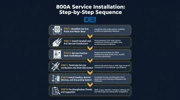
Step 6: Pre-Energization Checks and Inspection
Before requesting utility energization, the installing contractor must complete a full pre-energization checklist:
- Verify all terminations are torqued
- Confirm conductor phase identification
- Megohm-test insulation resistance on service conductors (per IEEE Std 43 guidance)
- Verify ground continuity
- Confirm switchboard is clean of debris
Pass the AHJ inspection before the utility will energize. Some projects at this ampacity also require a third-party commissioning review per ANSI/NETA ECS-2024 standards.
Common Installation Problems and How to Fix Them
Even experienced crews hit the same failure points on 800A installations — conductor sizing, clearance violations, and utility coordination are where most costly re-work originates.
Undersized or Improperly Paralleled Conductors
Problem: Service conductors are undersized for actual run length or parallel sets are installed with mismatched lengths or sizes.
Root cause: Conductor sizing was calculated without accounting for actual run length, voltage drop, or conduit type — or parallel runs were installed without matching conductor characteristics.
Fix: Size conductors using NEC Article 310 tables for the specific conduit type, temperature rating, and run length. For parallel runs, every conductor in each phase set must match in length, size, conductor type, and conduit material per NEC 310.10(H) — no exceptions.
Insufficient Working Clearance Around the Switchboard
Problem: Switchboard is positioned too close to walls, other equipment, or obstructions, failing NEC Article 110.26 clearance requirements.
Root cause: Equipment was placed based on floor plan dimensions without accounting for NEC clearances, which vary by voltage class and whether energized parts are exposed on one or both sides.
Fix: Verify working space dimensions against NEC 110.26 before setting the switchboard. If the space is already built out, the switchboard location must be revised — there is no waiver for clearance violations.
Utility Coordination Failures Causing Energization Delays
Problem: Project is ready to energize but the utility has not approved metering configuration, CT ratios, or service entrance design — causing significant schedule delays.
Root cause: Utility submittals went in late, or the utility's requirements — which vary by POCO — were never confirmed before equipment was specified.
Fix: Submit the utility application and design package during the design phase, not after equipment is delivered. Confirm CT metering requirements, service entrance configuration, and meter form with the utility before finalizing the single-line diagram.
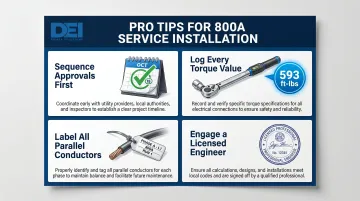
Pro Tips for a Successful 800 Amp Service Installation
These four practices prevent the most common causes of delay, rework, and liability on 800A installations.
Sequence approvals before ordering equipment. Switchboards and switchgear at 800A carry significant lead times. Ordering before utility approval and AHJ permit issuance risks receiving equipment that doesn't match the final approved design.
Record every termination torque value during commissioning. Research from FM Global found that loose connections at a 0.37 mm oscillation gap can drive wire temperatures to 593°C (1,100°F) — enough to ignite nylon-coated PVC insulation. A torque log protects the installing contractor if thermal failures surface later and is often required for project closeout.
Label every conductor in parallel sets at both ends. Color coding alone isn't reliable when multiple parallel sets run through the same conduit. Use permanent labels; meticulous phase identification here prevents costly troubleshooting later.
Engage a licensed electrical engineer for single-line diagrams and load calculations. AHJs in most jurisdictions require engineer-stamped drawings at 800A. An unlicensed design won't pass plan review.
Frequently Asked Questions
What size wire is needed for an 800 amp service?
Conductor sizing for 800A service depends on run length, conduit type (PVC vs. rigid metal), and conductor temperature rating. Parallel conductor sets are typically required at this ampacity, commonly two sets of 500 kcmil copper. Reference NEC Article 310 tables and have a licensed electrician confirm sizing for your specific installation conditions.
How many volts is an 800 amp service?
800A service is most commonly delivered at 277/480V three-phase for industrial facilities, or 120/208V three-phase for commercial buildings. Large residential or light commercial applications may use 120/240V single-phase. The voltage is determined by the utility and the facility's load requirements, not by the ampacity alone.
What NEC code articles govern 800 amp service installation?
Primary articles include Article 230 (service entrance), Article 240 (overcurrent protection), Article 310 (conductor sizing), Article 408 (switchboards), and Article 250 (grounding and bonding). All apply in combination for full code compliance.
Does installing 800 amp service require utility approval?
Yes, the local utility (POCO) must review and approve the service design, including metering configuration and service entrance details, before the project can be energized. This approval process should begin early in the project timeline to avoid delays.
Can a homeowner or general contractor install 800 amp service themselves?
800A service must be installed by a licensed electrical contractor with commercial/industrial experience. Most AHJs require engineer-stamped drawings at this service size, and utility interconnection requires formal approval. Unlicensed installation is both illegal and extremely dangerous at this scale.
What is the difference between an 800 amp service and an 800 amp subpanel?
An 800A service is the point where utility power enters the facility (governed by NEC Article 230), while an 800A subpanel is fed from the main service. The distinction matters for bonding and grounding: service equipment requires the main bonding jumper connecting neutral to ground; subpanels must keep neutral and ground buses separated.