Only qualified persons as defined by NFPA 70E should perform this work. These individuals must have formal training in energizing and de-energizing circuits, using personal protective equipment (PPE), and understanding NEC code requirements. A general electrician without specific switchgear experience is not prepared for this installation.
The consequences of improper installation are serious. Bus connection failures, grounding faults, failed inspections, and warranty voidance are common outcomes. In severe cases, improper installation can lead to arc flash incidents—events that occur 5 to 10 times daily in U.S. electrical equipment, resulting in approximately 7,000 burns, 2,000 hospitalizations, and 400 deaths per year.
This guide walks through the complete, correct installation of a Siemens switchboard per the official Siemens instruction manual (11-A-1077-01 Rev. 3), from pre-delivery preparation to pre-energization validation.
Key Takeaways
- Installation requires qualified personnel, NEC compliance, and Siemens factory drawings
- Verify a level foundation, correct conduit stub placement, and inspect all shipping sections before work begins
- Anchor, level, and shim each section before torquing bus splice and ground bus connections to spec
- Cable termination, lashing, and control wiring must meet both NEC and Siemens-specific requirements
- Complete a pre-energization inspection, megger test, and ground fault protection test before energizing
Installation Guide for Siemens Switchboards
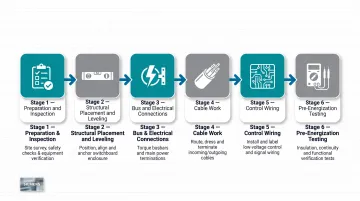
Siemens switchboard installation follows a defined sequence: preparation and inspection → structural placement and leveling → bus and electrical connections → cable work → control wiring → pre-energization testing. Shortcuts or out-of-sequence steps create long-term reliability and safety risks.
Larger switchboard lineups ship as multiple sections and require crane or forklift access, a level foundation prepared in advance, and access to factory-supplied general arrangement drawings before any installation work begins.
Prerequisites and Safety Considerations
Before installation begins, confirm:
- Working clearances per NEC Article 110.26: 3 ft 6 in. depth for 151-600V equipment (Condition 2), minimum width of 30 in. or equipment width, and minimum headroom of 6 ft 6 in.
- Level foundation capable of supporting equipment weight (sections can reach 2,600 lbs)
- Conduit stubs flush with or below finished floor level per NEC 408.5
- Factory general arrangement drawing showing section placement and shipping group sequence
Non-negotiables for safety:
- Only qualified persons trained per NFPA 70E, knowledgeable of NEC requirements, and authorized to lock out and tag circuits may perform installation work
- All power sources must be de-energized and isolated before any internal work per OSHA 29 CFR 1910.333
- Never force interlock devices or safety mechanisms
Equipment sourced from an approved Siemens OEM like DEI Power arrives pre-tested to UL 891 standards with factory drawings, rated configurations, and section markings — reducing the risk of field errors from incomplete documentation.
Tools and Parts Required
Lifting and placement equipment:
- Overhead crane with spreader bars or forklift with safety straps and proper balance
- Rigging capacity sized to section weights: up to 2,600 lbs per section for utility/metering sections per Siemens SPEEDFAX catalog
- For crane lifts, maintain sling angles above 30 degrees per ASME B30.9 (any lift below this threshold requires a Critical Lift Plan approved by a qualified person)
Hardware and fasteners:
- Factory-supplied splice plate kits (do not substitute with smaller or lower-grade hardware)
- Grade 5 or Grade 2 bolts as specified per section
- Belleville washers
- Calibrated torque wrench (ASME B107.300 compliant) capable of reaching 50 ft-lbs for single-bolt bus connections and 20 ft-lbs for four-bolt configurations
Testing tools for pre-energization:
- Megger (insulation resistance meter) for phase-to-phase, phase-to-ground, and neutral-to-ground tests
- Low-voltage high-current source for ground fault relay testing (where applicable)
- Auxiliary power source for operating electrically controlled devices during inspection
How to Install a Siemens Switchboard: Step-by-Step
Each step below maps directly to the sequence in the Siemens manual. Work through them in order — leveling and bus splice stages are particularly unforgiving if rushed.
Step 1 — Receiving and Pre-Installation Inspection
Upon delivery, verify shipment completeness against the packing list. Inspect for transit damage before unloading where possible; note visible damage on the delivery receipt with driver acknowledgment. Do not move equipment from its unloading position until the carrier has inspected damage.
For concealed damage, notify the carrier within 15 days. DEI Power customers should also contact sales@deipower.com within 5 days of receipt with photos and a detailed description of the issue.
Store indoors in a clean, dry environment. For extended storage, restore packing and add a 250-watt heat source per section to prevent condensation.
Step 2 — Foundation Prep and Section Positioning
Locate the installation area per the building plan and verify NEC 110.26 working clearances. Clean the mounting surface. Starting from the left end shipping group, maneuver each section into position using crane or forklift procedures.
Remove shipping skids, stand each section upright, and remove all packing and floor plates. Watch for conduit stubs above floor level — they can obstruct sliding.
Step 3 — Anchoring, Leveling, and Joining Sections
Level and align all shipping sections as a unit before tightening any anchor bolts. Use 4-inch square shims at anchor bolt locations where the floor is uneven—never force sections into contact by overtightening anchors, as this distorts cubicles.
Once leveled, tighten anchor bolts or weld to sills. Join adjacent shipping groups by bolting front and rear corner posts with 5/16-16 × 1.00-inch steel bolts torqued to 12 ft-lbs. For seismic installations, follow supplemental seismic instructions supplied with the equipment.
Step 4 — Bus Splice and Grounding Connections
With bus compartment barriers removed for access, assemble through-bus splice connections using the supplied splice plate kits. All contact surfaces must be clean and dry. Anti-oxidant compound is not required for indoor copper-to-copper joints — but is mandatory for copper-to-aluminum bimetallic joints.
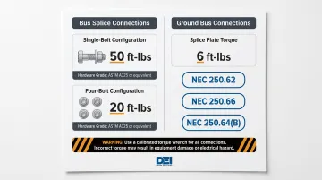
Torque single-bolt connections to 50 ft-lbs and four-bolt connections to 20 ft-lbs using the correct grade hardware. Only 25% of connections made without a calibrated torque wrench fall within specification—use a calibrated tool for all bus work.
Connect the ground bus splice plate and torque to 6 ft-lbs. Run grounding electrode conductors per NEC 250.62, 250.66, and 250.64(B), and confirm the main bonding jumper is installed and properly labeled for grounded service systems.
Step 5 — Cable Termination and Control Wiring
Route conduits and cable entries per the front elevation drawing, keeping conduits no more than 3 inches above the enclosure bottom (NEC 408.5). Pull cables sized to match lug barrel specifications, maintaining maximum bending radii and clearance from bus bars.
Key termination requirements:
- Aluminum cable: Clean contact surfaces with a wire brush and apply joint compound before terminating per NEC 110.14
- Cable lashing: Use nylon rope sized to the applicable short-circuit rating at specified intervals (consult Siemens manual 11-A-1077-01 for application-specific requirements)
- Control wiring across shipping splits: Trace wires using the factory-supplied wiring diagram and secure all field-installed wires with plastic ties to the cubicle structure
Post-Installation Checks and Validation
Before energizing, complete the full inspection checklist:
- Visually confirm no damage to bus supports or device mountings
- Check torque on all accessible bus bar connections
- Manually operate all circuit breakers and switches for alignment and proper function
- Confirm all temporary ties, blocking materials, and shipping supports have been removed
- Verify all covers are installed and conductors are not pinched
Insulation Resistance Testing
Using a megger, test phase-to-phase, phase-to-ground, phase-to-neutral, and neutral-to-ground — with the neutral isolated and all overcurrent devices open. Resistance readings of 100 megohms or greater at 1,000 VDC are required per NETA ATS Table 100.1 for 600V-class equipment.
Note: The commonly cited "1 megohm minimum" comes from IEEE 43, which applies to rotating machines — not switchgear. Low readings indicate a field wiring fault that must be resolved before energization.
Ground Fault Protection Testing
Ground fault protection is required per NEC 230.95 for 1,000A+ service disconnects on solidly grounded wye systems above 150V to ground. If your switchboard includes this protection, perform the full external and internal ground fault relay test per Sections 6.1 and 6.2 of the Siemens manual, and record all results on the ground fault test record forms.
Skipping this test violates NEC 230.95(C) and voids protection system assurance — which can result in inspection rejection and denied insurance claims.
Common Installation Problems and Fixes
Even experienced crews run into the same problems on Siemens switchboard installations. Most trace back to skipped documentation reviews, improper leveling, or incorrect hardware — issues that cause costly rework if caught late.
Uneven Sections and Misaligned Bus Bars
Problem: Adjacent shipping sections won't align properly for through-bus splice connections, or splice plates don't seat flush.
Likely cause: The foundation surface has high points or the sections were anchored before leveling was confirmed across all anchor points.
Fix: De-anchor, re-shim at all anchor bolt locations using 4-inch square shims, and re-level the entire shipping group before re-anchoring. Never use anchor bolts to force a section into contact with an uneven surface.
Incorrect Bus Splice Torque or Hardware
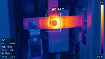
Problem: Bus connections overheat during initial operation, or connections fail insulation testing.
Likely cause: Substitute bolts (incorrect grade or size) were used, torque was applied without Belleville washers, or surfaces were contaminated with grease or anti-oxide compounds before assembly.
Fix: Follow these steps in sequence:
- Disassemble the joint and clean all mating surfaces with a mild cleaner — keep cleaning agents off insulation.
- Reassemble dry using only the factory-supplied splice plate hardware (no substitutions).
- Re-torque to specification per the hardware grade chart: 20 ft-lbs for 3/8-16 Grade 5, 50 ft-lbs for 1/2-13 Grade 5.
Thermal runaway from loose connections increases resistance, generates heat, and loosens the joint further — a compounding failure that correct torque prevents from the start.
Grounding Errors That Defeat Ground Fault Protection
Problem: The ground fault protection system trips unexpectedly or fails its field test after installation.
Likely cause: A grounding conductor was connected on the load side of the neutral disconnect link or ground fault sensor—bypassing the sensor and creating an unintended ground path that the relay detects as a fault.
Fix: Review the grounding schematic per the front elevation drawing; confirm all grounding conductors are on the line side of the sensor. Re-run the ground fault test per Section 6.1 of the Siemens manual after correction and record results.
Pro Tips for Installing Siemens Switchboards Effectively
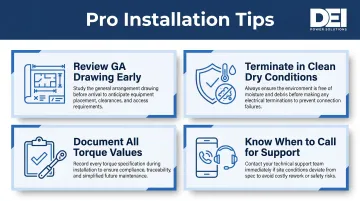
Keep these four practices in mind from first delivery to final sign-off:
- Review the general arrangement drawing before equipment arrives. Confirm anchor bolt layout, conduit stub locations, and section sequence in advance. Corrections at this stage cost hours; corrections after delivery can cost days.
- Never terminate cable in humid or dusty conditions. Clean, dry, temperature-stable environments prevent insulation contamination and connection degradation — especially critical for aluminum cable terminations.
- Document every torque value and hardware grade during bus splice assembly. Retain these records alongside ground fault test forms for the authority having jurisdiction and future maintenance reference.
- Know when to bring in commissioning support. Complex configurations — dual-fed systems, non-standard ground fault sensor placement, seismic-rated installations — benefit from on-site verification of coordination settings and operational training.
If your project involves a complex or custom configuration, DEI Power's engineering team can work through specifications, documentation, and layout requirements ahead of delivery — reducing field adjustments and keeping your schedule intact.
Conclusion
The quality of a Siemens switchboard installation directly determines its long-term safety, compliance, and reliability. A switchboard that's improperly leveled, incorrectly torqued, or energized without pre-testing creates risk rather than reliability.
Treat the general arrangement drawing, the torque specification chart, and the pre-energization checklist as non-negotiable. When the installation scope exceeds in-house switchgear experience, bring in qualified support early — before field problems become schedule problems. DEI Power's engineering team can assist with configuration questions and documentation review for UL 891-certified switchboard projects.
Frequently Asked Questions
What is the structure of a Siemens switchboard?
Siemens switchboards are free-standing, deadfront units rated up to 6,000A at 600V AC or less per UL 891 and NEMA PB2. A typical switchboard contains a service entrance section with main protective devices and distribution sections with branch devices, disconnect switches, metering equipment, and optional ground fault protection—all enclosed in grounded metal enclosures.
Who is considered a qualified person to install a Siemens switchboard?
A qualified person is trained and authorized to energize, de-energize, and ground circuits per established safety practices. They must know how to use PPE correctly, hold first aid training, and be knowledgeable of NEC requirements and applicable codes—not just general electrical licensing.
What NEC clearances are required for Siemens switchboard installation?
NEC Article 110.26 governs working clearances for front-accessible switchboards: 3 ft 6 in. depth for 151-600V equipment (Condition 2), minimum 30 in. width, and 6 ft 6 in. headroom. Conduit stubs must be flush with or below finished floor level per NEC 408.5, and conduits may not extend more than 3 inches above the bottom of the enclosure interior.
How do you test a Siemens switchboard before energizing?
Run a megger insulation resistance test across all phase, neutral, and ground combinations—100 megohms or greater at 1,000 VDC is required per NETA ATS. For units with ground fault protection, complete a GFP field test per NEC 230.95(C) using the push-to-test function and a simulated high-current test on the sensor.
What should you do if a Siemens switchboard is damaged during shipping?
Note visible damage on the delivery receipt with the driver's signature before accepting the shipment. Report concealed damage to the carrier within 15 days. Do not move the equipment from its unloading position until the carrier has inspected it, and notify the Siemens Sales Office immediately.
What is the continuous load limit for a Siemens switchboard?
Continuous load current must not exceed 80% of the main device's ampere rating unless it is rated for 100% loading. This limit applies equally to individual feeder and branch circuits; harmonic-producing loads may require further de-rating.