Introduction
Commercial switchboard installation is technically demanding work that carries significant safety and financial consequences when done incorrectly. Between 2012 and 2016, electrical distribution and lighting equipment fires caused an average of $718 million in property damage annually, with electrical failure or malfunction contributing to 75% of these incidents. This is not a DIY task or a job for general handymen: commercial switchboard installation requires high-voltage expertise, strict NEC code compliance, utility coordination, and the technical judgment to catch errors before they become arc flash hazards or failed inspections.
This guide covers commercial-scale installations only: switchboards rated 400A to 4000A serving industrial plants, data centers, hospitals, and utility substations. Residential panel upgrades are out of scope. The work must be performed by licensed electricians with commercial experience, working alongside project engineers, general contractors, and facility teams.
When installation is done incorrectly — under-torqued bus connections, skipped insulation testing, undersized short-circuit ratings — the results include arc flash incidents, thermal damage, failed AHJ inspections, and costly rework that delays project completion.
Given those stakes, every phase matters. This guide walks through the complete process: site prep, safety prerequisites, step-by-step execution, commissioning, and common problem resolution.
Key Takeaways
- Secure licensing, permits, utility coordination, and LOTO procedures before equipment arrives on site
- Installation follows seven phases: site prep, enclosure placement, conduit/conductors, bus terminations, breakers, control wiring, then commissioning
- Under-torqued bus bar connections cause thermal failures; always follow manufacturer torque specs exactly
- Commissioning must include insulation resistance testing, torque verification, ground continuity checks, and controlled energization
- Accurate single-line diagrams and UL 891-certified equipment cut field adjustments and change orders
Installing a Commercial Switchboard: What the Process Involves
Commercial switchboard installation spans four distinct phases that must be completed in sequence:
- Pre-installation planning and coordination – Permits, utility scheduling, site prep
- Physical placement and rough-in – Enclosure anchoring, conduit installation
- Electrical terminations and component installation – Bus connections, breaker installation
- Commissioning and inspection – Testing, energization, final sign-off
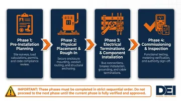
Skipping ahead — pulling conductors before the enclosure is anchored, or energizing before insulation testing is complete — typically results in failed inspections and costly field rework that pushes substantial completion back by days or weeks.
Timeline and Team Expectations
A standard commercial switchboard installation typically involves:
- Licensed electrician lead and assistant, coordinating with the general contractor, engineer of record, and local AHJ
- Physical installation runs 1–5 days, depending on system complexity
- Full project timeline stretches several weeks once permitting, utility coordination, and inspections are factored in
Prerequisites and Safety Requirements
Utility and Site Power Requirements
Before installation begins:
- Confirm incoming service size matches the switchboard's main bus rating
- Verify utility scheduling for service connection or de-energization
- Confirm the pad or mounting surface can support the switchboard's weight and dimensions (obtain specifications from manufacturer's submittal drawings)
Code and Permitting Non-Negotiables
NEC Article 408 governs switchboard installation requirements in the US, including:
- Working clearances: Minimum 3 feet in front of the switchboard per NEC 110.26 (Condition 1 for 151-600V equipment); 3 ft 6 in. for Condition 2 (concrete wall opposite) and 4 ft for Condition 3 (live parts on both sides)
- Dedicated electrical room conditions per NEC 110.26(E): no piping, ductwork, or foreign equipment in the space extending 6 feet above the switchboard
- Permits: Required from the AHJ before work begins; permits are valid for 180 days maximum
- Inspections: Required at rough-in and final energization
Arc Flash and LOTO Requirements
Even when working on de-energized switchboards, adjacent live equipment may be present. Workers must:
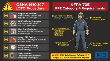
- Follow OSHA 1910.147 lockout/tagout procedures
- Wear arc flash PPE rated to the calculated incident energy for the work zone
- 600V switchboards default to Category 4 (40 cal/cm² minimum) per NFPA 70E Table 130.7(C)(15)(a)
- Obtain the arc flash hazard analysis from the engineer of record before work begins — if it's missing from the project package, request it before proceeding
Compatibility Checks Before Installation Day
- Short-circuit current rating (SCCR) must meet or exceed the available fault current at the installation point (from the engineer's short circuit study)
- Incoming conductor sizes and conduit entry points must match the switchboard's termination lugs
- Confirm the load schedule and get sign-off before breakers are ordered
If any of these checks fail, stop. Three rules apply before you proceed:
⚠️ Non-Negotiables:
- Do not proceed if available fault current exceeds the switchboard's SCCR
- Do not install without a valid permit
- Do not energize without AHJ approval
Tools and Materials Required
Before work begins, confirm every item on this list is on-site. Missing a torque wrench or a single conduit fitting on installation day costs time you don't have.
Essential Tools
- Torque wrench with appropriate bit set (torque specs are on the switchboard manufacturer's documentation)
- Calibrated insulation resistance tester (megohmmeter)
- Digital multimeter and voltage tester
- Conduit bending and wire pulling equipment
- Level for enclosure placement
Safety Equipment
- Arc flash-rated face shield, gloves, and clothing sized to the calculated arc flash boundary
- Insulated hand tools
- Voltage detectors
- Fall protection if working at height
Materials to Confirm Before Installation Day
- Switchboard enclosure, UL 891-certified for commercial low-voltage applications
- Main and branch circuit breakers per load schedule
- Incoming service conductors sized per NEC and engineer's specification
- Grounding electrode conductors and equipment grounding conductors
- Conduit, fittings, termination lugs, cable ties, and labels
- Manufacturer's wiring diagrams and submittals
How to Install a Commercial Switchboard: Step-by-Step
Commercial switchboard installation follows a strict sequence, from utility shutoff and LOTO through conductor termination, breaker installation, and controls wiring. Skipping steps or reversing the order creates rework that compounds both time and cost.
Step 1 — Coordinate Utility Shutoff and Implement LOTO
- Confirm with the general contractor and utility provider that incoming service is de-energized and tagged out
- Apply lockout devices to all energy sources
- Verify absence of voltage using a calibrated tester before any physical work begins
- Communicate the outage window to all affected building systems
Step 2 — Position and Anchor the Switchboard Enclosure
- Move the switchboard into position using appropriate lifting equipment (switchboards typically weigh 300+ pounds; consult manufacturer's rigging instructions)
- Level the enclosure, then anchor it to the mounting surface per manufacturer's requirements and any seismic zone requirements
- Confirm that all required clearances per NEC 110.26 are maintained on all access sides
Step 3 — Install Conduit, Pull Conductors, and Verify Sizing
- Install conduit entries into the switchboard's designated knockouts or through the bottom/top as specified in drawings
- Pull service entrance conductors and branch circuit feeders into the enclosure, leaving sufficient length for termination
- Verify conductor sizes against the engineer's schedule before cutting
- Confirm conduit fill does not exceed NEC Chapter 9 limits
Step 4 — Terminate Conductors at the Bus in the Correct Sequence
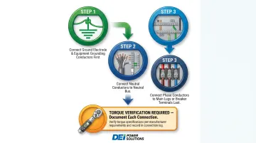
Critical sequence:
- Connect grounding electrode conductors and equipment grounding conductors first
- Land neutral conductors on the neutral bus
- Land phase conductors last, at the main lugs or main breaker terminals
Torque all terminations to the manufacturer's specified values using a calibrated torque wrench. Under-torqued connections are a leading cause of post-installation thermal failures. Document the torque applied to each connection.
Once all terminations are torqued and documented, verify phase rotation is correct using a phase sequence tester before proceeding.
Step 5 — Install Branch Circuit Breakers and Land Load-Side Conductors
- Install branch circuit breakers into their assigned positions per the approved load schedule
- Seat each breaker fully into its bus plug or bolt-on position and torque the line and load lugs to spec
- Land load-side conductors
- Label each circuit clearly at the breaker using circuit identification labels that match the panel schedule
- Dress conductors neatly using cable ties
Step 6 — Install Metering, Control Wiring, and Ancillary Components
If the switchboard includes digital meters, current transformers, shunt trip breakers, or ATS controls:
- Install and wire these per the manufacturer's wiring diagrams
- Verify CT polarity and connection before energization
- Confirm all control wiring is properly routed away from power wiring to minimize interference
With metering and controls in place, the switchboard is ready for pre-energization inspection and commissioning checks before the utility connection is restored.
Post-Installation Checks and Commissioning
Post-Installation Checks and Commissioning
With the physical installation complete, commissioning verifies that the switchboard is safe to energize and will perform as designed. Work through each step below before the AHJ inspection.
Insulation Resistance (Megger) Testing
Before requesting energization, perform insulation resistance testing on all power conductors—phase-to-phase and phase-to-ground—with the switchboard de-energized and breakers open.
Per NETA ATS Table 100.1:
- Test voltage: 1000V DC
- Minimum insulation resistance: 100 megohms for 600V class switchboard assemblies
- Control wiring minimum: 2 megohms
Low readings indicate insulation damage from shipping, handling, or pulling and must be resolved before energization.
Re-Verify Torque on All Connections
Re-verify torque on all bus connections, lug terminations, and neutral/ground connections using the documented torque values from the manufacturer. Cross-reference against the torque log created during Step 4.
Confirm that all covers, barriers, and arc flash labels are installed.
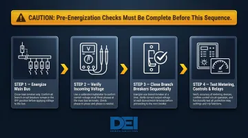
Perform a Controlled Energization Sequence
- Energize the main bus with all branch breakers in the OFF position
- Verify incoming voltage on all phases at the bus
- Close branch breakers one at a time, verifying voltage at each output
- Test any metering, control, and protective relay functions for correct operation per the engineer's commissioning checklist
Document All Commissioning Results
Document megger readings, torque logs, voltage measurements, and breaker test results, and retain the full package for both the AHJ inspection and the facility's permanent maintenance records.
Incomplete documentation is a leading cause of failed final inspections and delayed project closeout, per Eaton's NFPA 70B compliance white paper. Don't leave this step for the last minute.
Common Installation Problems and Fixes
Overheating at Bus Bar or Lug Connections After Energization
Problem: Thermal imaging or hot spots detected at connection points during or after initial energization.
Likely causes:
- Under-torqued or improperly seated conductor terminations
- Aluminum conductor oxidation not treated with antioxidant compound before termination (per NEC 110.3(B))
Fix: De-energize the affected circuit, re-torque the connection to the manufacturer's specified value, inspect the conductor end for oxidation or damage, and re-test with thermal imaging after re-energization.
Insulation Resistance Failure During Megger Testing
Problem: One or more conductors show low insulation resistance during pre-energization megger testing, preventing the switchboard from being safely energized.
Likely causes:
- Conductor insulation damaged during pulling (pinched in conduit, cut on a sharp edge)
- Shipping damage to internal components
- Moisture in conduit that has not been cleared
Fix: Identify the specific conductor or component showing the fault by testing section by section. Inspect conduit runs for sharp edges, pull the conductor back to inspect for physical damage, and clear any moisture from conduit before re-testing. Replace damaged conductors if necessary.
Branch Circuit Breaker Trips Immediately When Loaded
Problem: One or more branch breakers trip on first load application even when load appears within rated capacity.
Likely causes:
- Breaker installed in the wrong position for its rating
- Load schedule contains errors and the actual connected load exceeds the breaker's trip rating
- Phase imbalance causing neutral overcurrent on multi-wire branch circuits
Fix: Cross-reference the breaker rating against the actual connected load using a clamp meter at the load terminals. Verify the load schedule against as-built conditions. Check phase balance across the bus and redistribute loads if needed. Always identify the root cause before resetting and re-energizing.
Pro Tips for Installing a Commercial Switchboard Effectively
Schedule the AHJ inspection early. In some jurisdictions, rough-in inspections are required before the enclosure is closed and conductors are fully terminated. Know the local inspection sequence and book inspectors before installation begins — not after.
Document every stage with sequential photos. Capture the enclosure before and after conductor termination, the torque wrench on connections, the interior before covers go on, and final circuit labeling. Solid photo documentation protects the contractor if questions arise later and gives the AHJ inspector exactly what they need.
Run a megger test before energization — every time. Shipping and handling can damage conductor insulation or internal components without any visible sign. A pre-energization insulation resistance test is the most reliable way to catch these issues before they become arc flash events or equipment failures.
Confirm UL 891 certification and documentation before the switchboard ships. A unit that arrives on site without proper certification paperwork may fail inspection regardless of installation quality. Verify that the manufacturer provides full engineering documentation, wiring diagrams, and accurate load schedule configurations — DEI Power's UL 891-certified switchboards ship with all of this included, which cuts field troubleshooting time significantly.
Conclusion
Installation quality determines the long-term safety, reliability, and code compliance of a commercial power distribution system. Poor terminations, skipped tests, and improper clearances rarely reveal themselves immediately — they create expensive failures under load.
The best commercial switchboard installations result from close coordination between the engineer of record, the licensed electrician, the general contractor, and the switchboard manufacturer — starting from specification and submittal review, not just on installation day.
Getting that coordination right starts before the equipment ships. A few factors that consistently separate successful installations from costly ones:
- Accurate specs from the start — voltage, amperage, number of sections, and feeder configurations confirmed before manufacturing begins
- UL 891-certified equipment — factory-tested assemblies that arrive ready for installation without field modifications
- Clear documentation — accurate single-line diagrams, torque specs, and wiring schedules that reduce guesswork on the jobsite
If you're sourcing switchgear for an upcoming project, DEI Power manufactures UL 891-certified low-voltage switchboards (400A–4000A) with in-house engineering support and fast lead times from their Ontario, California facility. Contact their team at sales@deipower.com or (866) 773-8050 to discuss specifications.
Frequently Asked Questions
How much does it cost to replace and install a new switchboard?
Commercial switchboard installation costs vary based on switchboard size, amperage, number of circuits, site complexity, and local labor rates. Permitting, engineering studies (short-circuit, coordination, arc flash), and utility coordination are frequently overlooked in initial budgets. For precise figures, consult a licensed electrical estimator or industry cost guides like RSMeans Electrical Costs Data.
How long does it take to install a new switchboard?
Commercial switchboard installation typically takes 1–5 days for the physical work, but the full project timeline—including permitting, utility coordination, AHJ inspections, and commissioning—often spans several weeks. System complexity and site conditions are the primary drivers of project duration.
How are switchboards wired?
Incoming service conductors land at the main lugs or main breaker first—grounding and neutral before phase conductors—then power distributes through copper or aluminum bus bars. Branch circuit breakers connect from there, with load-side conductors routed to individual circuits per the approved load schedule and manufacturer's wiring diagrams.
How much will an electrician charge to replace a circuit breaker?
Breaker replacement costs vary by breaker type, amperage rating, and whether the work requires partial de-energization of the switchboard. In a commercial switchboard, this work must be done by a licensed electrician and may require an AHJ permit depending on jurisdiction. Contact a licensed electrical contractor for project-specific estimates.
Do you need a permit to install a commercial switchboard?
Yes, a permit is required in virtually all US jurisdictions for commercial switchboard installation. The permit is pulled from the local AHJ before work begins, and the installation will require one or more inspections—typically at rough-in and at final energization—before the system can be placed into service.
What is UL 891 and why does it matter for commercial switchboard installation?
UL 891 is the UL standard for low-voltage switchboards that verifies the switchboard has been designed, built, and tested to meet established safety and performance requirements. Specifying UL 891-listed equipment means the switchboard will satisfy AHJ inspection requirements, comply with insurance and code mandates, and hold up under the fault current conditions present at your site.