This guide covers site selection methodology, preparation requirements, installation sequencing, validation procedures, and failure mode correction for outdoor power distribution units.
Key Takeaways
- PDU placement decisions—enclosure rating, load proximity, clearances, and environmental exposure—directly determine installation safety and long-term compliance
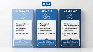
- Match enclosure rating to environment: NEMA 3R for rain/sleet, NEMA 4 for washdown areas, NEMA 4X for coastal or chemical exposure
- Confirm site readiness (grounding, conduit routing, structural support, NEC clearances) before positioning or connecting the unit
- Post-installation validation—insulation resistance, load testing, and weatherproofing checks—is required before energizing
- Most outdoor PDU failures trace back to moisture ingress, poor grounding, or inadequate conduit sealing—all preventable with proper pre-installation planning
Where to Install an Outdoor Power Distribution Unit
Location is the most consequential decision in any outdoor PDU installation. Poor placement leads to compounding failures: ongoing exposure risk, restricted maintenance access, NEC working clearance violations, or excessive cable runs that strand the unit too far from its load. The downstream consequences include rework, code violations, equipment failure, and safety incidents.
Primary Installation Environments
Construction and industrial jobsites: Units are positioned near the generator or utility tie-in point and located centrally relative to tool and equipment loads. Distance from the power source and cable routing paths drive placement decisions. The unit must remain accessible for inspection but protected from vehicular traffic and physical damage.
Commercial campuses, outdoor events, and public areas: PDUs are sited at the perimeter of the active zone or integrated into existing infrastructure such as bollards or concrete pads. Aesthetic integration and lockable access become key considerations. The installation must balance visibility for maintenance with security against tampering or unauthorized access.
Utility substations and industrial facilities: PDUs are placed on dedicated concrete equipment pads or mounted to structural steel frames. Proximity to switchgear, transformer outputs, and maintenance walkways determines exact siting. These installations require coordination with utility standards and long-term operational access planning.
Physical Placement Requirements
Every outdoor PDU must meet baseline physical placement criteria:
- Stable mounting surface: The unit must be positioned on a level, structurally sound surface or securely wall- or pole-mounted using manufacturer-specified fasteners
- Drainage: Never place a PDU in a depression where water can pool; units must be elevated off the ground surface where flooding or runoff is possible
- Working clearance: The front of the unit must maintain NEC-mandated working clearance—typically 36 inches minimum for 0-150V installations, increasing to 42 inches at 151-600V (Condition 2) and 48 inches at 151-600V (Condition 3)—verify against the applicable NEC edition and local amendments
- Access: Mounting height and orientation must allow safe access for operation, maintenance, and inspection
NEMA Enclosure Rating: A Location-Matching Decision
The NEMA enclosure rating must match the specific outdoor micro-environment, not just "outdoor" as a general category:
- NEMA 3R: Baseline for units exposed to rain, sleet, and snow; provides protection against falling precipitation and external ice formation but does not seal against hosedown or dust ingress
- NEMA 4: Required where hose-directed water, windblown dust, or splashing water is present; provides watertight and dusttight protection
- NEMA 4X: All Type 4 protections plus corrosion resistance; required for coastal environments, chemical exposure, or wash-down areas; passes an additional 200-hour salt spray test beyond the standard Type 4 rating
Using a NEMA 1 or NEMA 2 enclosure outdoors is a code violation and an immediate safety hazard. Approximately 40% of outdoor electrical breakdowns are directly linked to moisture ingress and corrosion—the majority traceable to incorrect enclosure selection.
Permanent vs. Temporary Outdoor Installations
Enclosure selection is only part of the equation — how long the installation stays in place shapes every other requirement.
Permanent installations must meet full NEC requirements for Articles 230, 240, and 300, including:
- Structural mounting to a fixed surface or equipment pad
- Weatherproof conduit with listed fittings throughout
- Dedicated grounding electrode system
- Permit approval in most jurisdictions before energizing
Temporary installations — construction sites and events — use portable PDUs with weather-resistant enclosures and must still comply with OSHA 29 CFR 1926.404 and NEC Article 590 temporary wiring rules. Critical requirements include:
- GFCI protection on all 120V, single-phase, 15A and 20A receptacles not part of permanent wiring
- Units must not be placed directly on wet ground
- PDUs must be kept clear of foot and vehicle traffic paths or protected by cable ramps and barriers
- GFCI-protected circuits required whenever installation is within 6 feet of water or in a construction setting
Even temporary outdoor PDUs must maintain working clearance and appropriate enclosure ratings for the exposure environment.
Before You Begin: Prerequisites and Site Readiness
Installation must not proceed until all site readiness criteria are satisfied. Skipping these steps is the primary cause of rework and commissioning delays.
Pre-Installation Verification Checklist
- Power source: Confirm ampacity, voltage, phase configuration (single-phase vs. three-phase), and available fault current match the PDU rating
- Conduit routing: Clear routing paths before finalizing placement; verify burial depths (NEC 300.5) and support intervals are code-compliant
- Structural anchor points: Confirm mounting surface is rated for the unit's weight plus wind load — concrete pads, wall/pole mounts, and rooftop installations each have distinct load requirements
- Grounding infrastructure: Verify that the grounding electrode system meets NEC requirements, including conductor size and routing path from the PDU location
Non-Negotiable Requirements
Installation cannot proceed if:
- The enclosure IP/NEMA rating is mismatched to the environment
- The working clearance cannot be maintained per NEC 110.26
- Grounding infrastructure is absent or undersized
- The power source exceeds the PDU's rated input
- Permit approval has not been secured (where required by local jurisdiction)
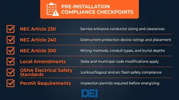
Compliance Checkpoints
Confirm that the following codes and standards are addressed before installation:
- NEC Article 230: Service entrance requirements, conductor sizing (125% of continuous load), drip loops, raintight raceways
- NEC Article 240: Overcurrent protection, readily accessible devices
- NEC Article 300: Wiring methods, burial depths, corrosion protection, raceway sealing at temperature transitions
- Local amendments: Verify jurisdiction-specific modifications to the NEC
- OSHA electrical safety standards: Applicable to the jobsite type (construction, industrial, utility)
- Permit requirements: Most jurisdictions require electrical permits for new installations or alterations
Starting with equipment pre-configured to your site's voltage, load, and enclosure requirements — like DEI Power's custom outdoor switchgear solutions in NEMA 3R enclosures from 400A to 4000A — eliminates the most common source of field rework before installation begins. Their in-house engineering team provides specification review, layout development, and code compliance verification, reducing change orders in the field.
How to Install an Outdoor PDU: Step-by-Step
Outdoor PDU installation follows a fixed sequence. Rushing to energize before weatherproofing and grounding are complete is the leading cause of field failures and safety incidents.
Step 1: Prepare the Installation Site
Mounting surface: Confirm the surface is level, structurally sound, and properly drained. For concrete pad installations, ensure the pad is cured and capable of supporting the equipment weight. For wall or pole mounts, verify that fastener locations align with structural members.
Conduit installation: Run conduit from the power source to the PDU mounting location using weatherproof conduit bodies and fittings rated for outdoor use. Install conduit with proper slope to allow drainage. At enclosure entry points, use watertight conduit hubs with O-ring seals.
Conductor pull: Pull conductors through conduit, leaving sufficient length inside the enclosure for termination (typically 6-12 inches of slack). Use conductors rated for wet locations (THWN, XHHW) per NEC 300.9. Form drip loops at conduit entries to prevent water from following conductors into the enclosure.
Step 2: Position and Secure the Unit
Set and level: Place the PDU onto the pad or mount it to the wall/pole/structural frame using manufacturer-specified fasteners and torque values. Verify the unit is level in both horizontal axes using a spirit level.
Working clearance verification: Before finalizing placement, confirm that the working space in front of the unit meets NEC 110.26 requirements (minimum 36 inches for most installations, more at higher voltages or certain exposure conditions). Confirm the door swings clear.
Fastener torque: Torque all mounting fasteners to manufacturer specifications. NFPA 70B (2023 edition) now mandates (not recommends) that all accessible electrical hardware connections be torqued per manufacturer data.
Step 3: Make Electrical Connections
Feeder connections: Connect incoming feeder conductors to the main breaker or main lug terminals per the wiring diagram. Observe phase rotation for three-phase units (typically A-B-C or L1-L2-L3). Torque all terminations to specifications.
Grounding: Connect the grounding conductor to the grounding bus. Verify continuity between the grounding bus and the enclosure. For separately derived systems, install a grounding electrode conductor to the grounding electrode system.
Conduit sealing at every entry point:
- Install weatherproof conduit hubs at all conduit entry points
- Seal unused knockouts with rated plugs
- Where conduit crosses temperature zones, use NEC 300.7(A)-compliant sealing compound — electrical duct seal, not expanding foam — to block warm air circulation and condensation
Branch circuit wiring: Connect branch circuit wiring or outlet wiring as applicable, maintaining proper conductor identification and torque specifications.
Step 4: Complete Weatherproofing and Grounding Verification
Seal inspection: Inspect all conduit entries, enclosure seals, and gasketed door seals before closing the enclosure. Verify that door gaskets are intact and properly seated.
Ground continuity test: Use a continuity tester to verify the ground conductor path from the grounding bus through all equipment grounding paths. Resistance should be near zero.
Do not energize until all of the following are confirmed:
- Weatherproofing complete at all entries and seals
- All terminations torqued to specification
- All conductors properly identified
- All unused knockouts sealed or plugged
Post-Installation Checks and Validation
Before energizing the system, perform the following validation sequence:
Pre-Energization Testing
Insulation resistance (megohm) test: Per ANSI/NETA ATS-2017 Table 100.1, test all conductors at the appropriate DC test voltage:
- 250V-rated equipment: Minimum 25 megohms at 500V DC
- 600V-rated equipment: Minimum 100 megohms at 1,000V DC
Readings below these thresholds indicate insulation damage, moisture ingress, or wiring faults. Do not energize until the fault is corrected and retest confirms acceptable values.
Termination verification: Before closing the main breaker, confirm all three of the following:
- All terminations are torqued to specification
- No conductors are pinched by the enclosure door or conduit fittings
- All branch breakers are in the off position
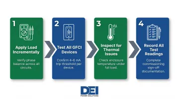
Functional Testing After Energization
Work through these steps in sequence:
Apply load incrementally and verify voltage at each outlet or branch circuit. Measure under load to confirm proper phase balance and adequate conductor sizing.
Test all GFCI devices using the test button. UL 943 defines Class A GFCI devices as tripping at 4 to 6 milliamps of ground-fault current — verify correct operation before commissioning.
Inspect for thermal and operational issues — enclosure heating, unusual sounds, or breaker trips all point to wiring errors or load calculation mistakes. Measure enclosure temperature under load to confirm it stays within equipment ratings.
Record all test readings and sign off on the commissioning record before handover. Retain copies for maintenance records and future troubleshooting.
Common Outdoor PDU Installation Problems and Fixes
The majority of outdoor PDU installation failures trace to three predictable errors: enclosure-environment mismatch, inadequate grounding, and poor conduit sealing. All are avoidable with correct pre-installation planning.
Moisture Ingress Into the Enclosure
Problem: Water enters the PDU enclosure through conduit entries or failed door gaskets, causing breaker trips, corrosion, or ground faults.
Likely cause: Conduit hubs not sealed with appropriate rated compound; conduit installed without drip loops; enclosure NEMA rating underspecified for the actual environment.
Fix: Drain and dry the enclosure completely. Install conduit sealing fittings and drip loops on all conduit entries. Replace the unit if the enclosure rating is mismatched to the site. Upgrade to NEMA 4X in wash-down or high-moisture environments.
Ground Fault Trips at Energization
Problem: GFCI breakers or ground fault protective devices trip immediately or intermittently on first energization.
Root cause: Conductor insulation damage during pull-through; conductor pinched by enclosure or conduit fitting; moisture already present in the conduit system creating a leakage path to ground.
Fix:
- Perform a megohm test on all conductors before re-energizing
- Inspect all conduit entry points and the enclosure interior for damaged insulation
- Dry the conduit run with a blower or allow adequate drying time before re-energizing
- Replace any conductors with compromised insulation
Enclosure Overheating Under Load
Problem: The enclosure exterior becomes excessively hot during normal operation, or thermal breakers trip under rated load.
Likely cause: Unit is installed in direct sun exposure without shade or ventilation; ambient temperature exceeds the PDU's rated operating temperature; the unit is undersized for the connected load.
Fix:
- Relocate or shade the unit to reduce solar heat gain
- Verify the connected load stays at or below 80% of the PDU's rated ampacity — the NEC 125% continuous load rule requires conductors and overcurrent devices sized at 125% of continuous load
- Specify a unit rated for the actual temperature range if ambient conditions regularly exceed the equipment rating
- Apply temperature-adjusted conductor sizing for direct-sun installations: NEC Table 310.15(B)(2)(a) shows a 75°C-rated conductor at 40°C ambient retains only 88% of its table ampacity
Pro Tips for Installing Outdoor PDUs Effectively
Three installation practices separate smooth outdoor PDU projects from costly mid-project rework.
Route Conduit Before Placing the PDU
The most common cause of mid-project rework is positioning the PDU first, then discovering the conduit path is impractical, code non-compliant, or structurally problematic. Route conduit on paper first, confirm the path is viable, and let the conduit endpoint determine final PDU placement — not the other way around.
Document the As-Built Installation
Before closing the enclosure, photograph conduit routing, conductor color coding, termination torque values, and GFCI test results. Studies show that sites without as-built records consistently experience longer fault resolution times and higher maintenance costs. That documentation also supports permitting sign-offs and future troubleshooting.
Know When to Bring in an Engineer
Some installations require electrical engineering review before work begins. These include:
- Three-phase outdoor distribution systems
- High-amperage feeder connections
- Utility interconnection points
- Permanent siting in flood-prone or corrosive industrial environments
Proceeding without that review creates liability, code exposure, and voided equipment warranties. NFPA 70B and NFPA 70E provide the standards for electrical maintenance and safety programs that support long-term reliability.
Frequently Asked Questions
Where should a PDU be installed in a rack?
For indoor rack PDUs, vertical 0U installation at the rear of the rack is most common as it preserves rack unit space. For outdoor applications, the equivalent is mounting the unit on a structural surface or pad that keeps it elevated, accessible, and within NEC-required working clearance (minimum 36 inches in front).
What are the different types of PDUs?
PDUs are categorized by functionality: basic (passive distribution), metered (local display), monitored (remote visibility), and switched (remote outlet control). For outdoor environments, the enclosure type and environmental rating (NEMA 3R, 4, 4X) are additional classifications that determine where each can be safely installed.
Is a PDU just a power strip?
No. A power strip is a basic consumer device with no circuit protection or environmental rating, while an industrial or outdoor PDU includes main breakers, branch circuit protection, proper grounding infrastructure, and weatherproof enclosures rated for specific environments—making the two fundamentally different in safety standard and application.
What NEMA rating do I need for an outdoor PDU?
NEMA 3R covers standard rain and sleet exposure. NEMA 4 is required where hose-directed water or windblown dust is present, and NEMA 4X adds corrosion resistance for coastal, chemical, or wash-down environments. Match the rating to the specific site exposure—"outdoor" alone is not a sufficient specification.
Can an outdoor PDU be installed directly on the ground?
Direct ground placement is not acceptable for permanent installations. Units must be mounted on a concrete pad, structural bracket, or elevated frame to prevent moisture ingress, maintain working clearance, and satisfy NEC requirements. Temporary installations still require elevation off wet surfaces and protection from physical damage.
What is the minimum clearance required around an outdoor power distribution unit?
NEC Article 110.26 generally requires a minimum of 36 inches of clear working space in front of electrical equipment at typical voltages (0-150V), with greater clearances required at higher voltages and different exposure conditions. Verify the exact requirement against the applicable NEC edition and any local amendments before finalizing placement.
Need outdoor-rated switchgear engineered for your specific site conditions? DEI Power manufactures UL 891-certified low-voltage switchgear and power distribution equipment with voltage options from 120V to 480V and amperage ratings from 400A to 4000A. Their in-house engineering team provides specification review, layout development, and code compliance verification to eliminate field mismatches before installation begins. Contact DEI Power at (866) 773-8050 or sales@deipower.com for project-specific configuration support.