Introduction
NEMA 3R enclosure installation is moderately complex—not a plug-and-play task. The enclosure's weatherproofing effectiveness depends entirely on how it is installed, not just how it was manufactured. Even small shortcuts can permanently void its protection rating.
Common installation shortcuts that compromise weatherproofing:
- Using wrong fittings on conduit entries
- Blocking intentional drain holes
- Drilling through enclosure walls instead of using mounting flanges
- Skipping grounding verification before energizing
Any of these errors can cause water intrusion or grounding failures that wouldn't show up until the enclosure is already compromised.
Installation should be handled by licensed electricians or trained field technicians familiar with NEC requirements, grounding and bonding standards, and enclosure-specific mounting requirements. Improper field modifications by unqualified personnel are one of the most common causes of premature enclosure failure.
This guide walks contractors, engineers, and facility teams through the full installation process—from site preparation and conduit entry to grounding, sealing, and post-installation validation—so the enclosure performs as rated for its full service life.
Key Takeaways
- NEMA 3R enclosures are weather-resistant, not watertight; use rated fittings and maintain drainage to preserve that protection
- Route conduit through the bottom when possible; top entry requires NEMA 3R-rated raintight hubs
- Never drill mounting holes through the enclosure body—use only designated mounting flanges
- Ground and bond all metallic components to a single verified grounding point before energizing
- Run post-installation validation checks before energizing the system
Prerequisites and Safety Considerations
Before installation begins, confirm these critical requirements:
Mounting Surface Verification
- Wall, concrete pad, or pole must be structurally sound and capable of supporting the full loaded weight
- Surface must be level—any unevenness requires correction with shims before fastening
- A twisted enclosure frame prevents the door from sealing properly, creating gaps for weather ingress
NEC 110.26 Workspace Clearance (Mandatory Code Requirement)
- Minimum depth: 3 feet for 0-150V systems, up to 5 feet for 601-1000V (Condition 3)
- Minimum width: 30 inches or equipment width, whichever is greater
- Minimum height: 6 feet 6 inches or equipment height, whichever is greater
- Door must open at least 90 degrees without obstruction
These clearances apply to outdoor NEMA 3R installations just as they do indoors.
Environmental Hazard Check
Verify the installation site does not expose the enclosure to hazards beyond NEMA 3R limits:
- Hose-directed water
- Windblown dust
- Corrosive agents
- Submersion risk
If any of these conditions exist, specify a higher rating (NEMA 4, 4X, or 6) before proceeding.
Pre-Installation Verification
- Confirm the enclosure's UL listing label is intact and legible
- For installations housing outdoor-rated power distribution equipment (such as UL 891-certified switchboards per the NEMA 250 enclosure standard), verify internal component compatibility with the enclosure's rated environment before proceeding
- Confirm voltage and amperage compatibility between the enclosure and housed equipment
- Verify seismic compliance for your zone if required
- Confirm the enclosure layout allows adequate service access once installed
Tools and Materials Required
Essential Tools
- Torque wrench
- Spirit level
- Power drill
- Socket set
- Knockout punch (hydraulic or manual)— required for clean, burr-free holes
Twist-drilled holes leave rough edges that damage cable insulation and prevent watertight gland seating. UL document 00-UM-C0860 establishes that field-cut holes must maintain enclosure integrity — knockout punches produce properly dimensioned openings that preserve the UL listing.
With tools confirmed, verify that every material entering the enclosure meets the same environmental rating.
Required Materials
All fittings must be rated NEMA 3R or higher:
- Conduit hubs rated for wet locations
- Cable glands listed for outdoor use
- Hole plugs rated NEMA 3R minimum
Using a lower-rated fitting on any entry point downgrades the entire assembly to that fitting's rating.
Mounting hardware:
- Hot-dip galvanized fasteners (meeting ASTM A153) OR stainless steel
- NEC 300.6 requires protective coatings on ferrous metals in outdoor locations—use only corrosion-resistant hardware
How to Install a NEMA 3R Enclosure (Step-by-Step)
Installation follows a strict sequence: structural integrity first, then conduit entries, then internal wiring. Skipping steps or reversing the order creates compounding problems that are difficult to diagnose after the enclosure is closed.
Step 1—Prepare and Mount the Enclosure
Clean the mounting surface, shim any uneven areas, and place a spirit level on the enclosure before final torquing.
For mounting:
- Secure the enclosure using external mounting feet or flanges only
- Never drill through the back wall — this permanently voids the NEMA rating
- Confirm the enclosure is plumb and level before torquing fasteners
- An out-of-level installation twists the frame and prevents the door from sealing correctly
Step 2—Create Conduit and Cable Entries
With the enclosure secured, create entries before any internal components are installed — it's easier to work cleanly in an empty box.
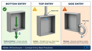
Bottom entry is preferred for all NEMA 3R installations. Use a knockout punch for clean, accurately sized holes — gravity directs water away from internal components.
Top entry, when unavoidable, requires a listed raintight hub (Myers Hub type) with a sealing gasket. Standard locknuts and bushings are not watertight under NEC 312.2 — moisture will track down conduit threads directly onto live components. Using indoor NEMA 1 fittings on an outdoor enclosure violates NEC 314.15.
Side entries require a drip loop formed in the cable below the entry point. Water must fall off the lowest point of the loop before the cable rises into the fitting — without this, capillary action pulls moisture straight into the enclosure.
Step 3—Install Internal Components and Wiring
Mount components in this sequence:
- Subpanel first
- DIN rails
- Circuit breakers and other components
Follow a heavy-low, light-high layout — heavier items near the bottom keep the center of gravity stable.
For wiring:
- Route conductors using wire ducts or cable ties to prevent contact with sharp edges
- Leave a service loop at each termination point for future maintenance
- Keep at least 20-25% of internal volume clear for airflow and thermal management
For installations housing large switchgear — such as switchboards rated 400A to 4000A — confirm the layout supports required working clearances and unobstructed service access before finalizing component placement.
Step 4—Ground and Bond All Components
NEC 250.96(A) requires bonding all metal non-current-carrying parts that serve as grounding conductors. Do not skip this step — verify it before closing the enclosure.
- Connect the enclosure body's grounding lug directly to the equipment grounding conductor
- Bond the door to the body with a flexible braided bonding strap
- Terminate the back panel, metallic conduits, and all equipment grounds at a single verified grounding point
- Remove nonconductive coatings (paint, enamel) at threads and contact points, or use fittings rated to cut through them
This creates a continuous low-impedance fault path required for safe overcurrent response.
Step 5—Seal, Close, and Finalize
With grounding verified, the enclosure is ready to close — but the final checks matter as much as the installation steps that preceded them.
- Plug all unused knockouts with NEMA 3R-rated plugs
- Verify weep holes at the base are completely unobstructed — these are intentional drainage features, not defects
- Close the door and engage all latches to confirm they draw the door evenly against the gasket
For labeling:
- Apply arc flash labels per NEC 110.16(B) — required on service and feeder equipment rated 1,000A or more (2023 NEC)
- Add circuit identification labels both inside and outside the enclosure
Post-Installation Checks and Validation
Visual and Structural Checks
Before energizing, confirm:
- Enclosure is plumb and all fasteners are properly torqued
- Door gasket compresses evenly across its full perimeter
- All conduit entries use rated hubs with no raw metal edges exposed at knockout holes
Pre-Energization Electrical Tests
Following ANSI/NETA ATS-2025 acceptance testing protocols:
- Perform continuity tests on all wiring to confirm no faults
- Run insulation resistance tests
- Verify grounding and bonding continuity from all metallic components back to the grounding point
These tests catch installation errors before they become live faults. Once electrical tests pass, a final visual comparison confirms the installation meets NEMA 3R requirements across all key points.
Correct vs. Incorrect Installation Indicators
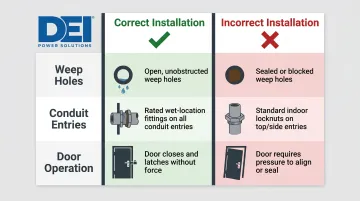
| Indicator | Correct | Incorrect |
|---|---|---|
| Weep holes | Open and unobstructed | Sealed or blocked by debris |
| Conduit entries | All use rated wet-location fittings | Standard indoor locknuts on top/side entries |
| Door operation | Closes and latches without force | Requires pressure to align or seal (suggests mounting distortion) |
Document test results and visual findings before commissioning — inspectors and facility teams will expect this record, and it protects against liability if a fault emerges later.
Common Installation Problems and Fixes
These are the three most common field failures on NEMA 3R installations—along with their causes and step-by-step fixes.
Non-Rated Fittings on Top or Side Conduit Entries
Moisture entering through fitting threads is one of the most frequently reported NEMA 3R failures. It drips directly onto live internal components and is often misdiagnosed as a seal failure elsewhere.
The root cause is almost always the same: standard NEMA 1 locknuts or indoor conduit fittings used in place of NEMA 3R-rated raintight hubs. Any listed conduit fitting is not automatically acceptable for outdoor wet locations.
Fix:
- Remove non-compliant fittings
- Replace with NEMA 3R-rated raintight hubs on all top entries
- For existing side entries, add a drip loop so water falls away naturally rather than tracking into the fitting
Blocked or Sealed Weep Holes
Condensation builds inside the enclosure and reaches internal components, causing corrosion or electrical faults with no obvious sign of water entry from outside. It happens when weep holes are sealed with silicone or foam by an installer who mistook them for a defect, or when they clog with mud, insects, or debris over time.
Fix:
- Clear weep holes using a probe or compressed air
- Add weep hole inspection to routine maintenance checks
- Never seal weep holes — NEC 314.15 permits drainage openings up to 1/4 inch in wet-location boxes; they are a required design element, not a defect
- Eaton's NEMA 12-to-3R conversion guidance specifically requires removing the drain plug, confirming that weep holes are a defining feature of the NEMA 3R rating
Door Misalignment and Latch Failure
The door won't close flush, the latch won't engage, or the gasket compresses unevenly — any of these leaves a gap for weather ingress. Three causes account for most cases:
- The enclosure was mounted to an uneven surface, twisting the frame under bolt torque
- Internal wiring or components shifted during installation and now block the door path
- Hinge pins have loosened from vibration
Fix:
- Loosen all mounting fasteners
- Insert shims behind mounting feet to create a true level plane
- Re-torque evenly
- Inspect the internal layout with the door open to confirm no component or wire bundle is interfering with the door swing
- Tighten or replace hinge pins as needed
Pro Tips for Installing NEMA 3R Enclosures Effectively
Plan Conduit Routing Before Mounting
- Map all entry points, quantities, and directions on paper or in field drawings first
- This prevents the common mistake of adding entries after mounting, which forces awkward top-side entries that compromise weather resistance
Combat Condensation in High-Temperature-Swing Regions
- Install a small thermostatically controlled anti-condensation heater inside the enclosure during commissioning
- Condensation from thermal cycling is one of the most underestimated sources of internal moisture in outdoor NEMA 3R installations — and one of the easiest to prevent with a low-cost heater spec'd at commissioning
Document the Installation Thoroughly
- Photograph the enclosure interior before closing (showing conduit entries, grounding connections, and component layout)
- Record torque values for mounting fasteners
- File the manufacturer's installation sheet with project documentation
- This documentation is critical for warranty claims, AHJ inspections, and future maintenance
Know When to Escalate
- If the site has salt air exposure, frequent high-pressure washdowns, or chemical vapor risk that was not identified during planning, stop and reassess the enclosure rating before proceeding
- Using a NEMA 3R enclosure in conditions it was not designed for costs far more to fix than specifying the correct rating upfront
- When in doubt, consult the equipment manufacturer or a licensed engineer. If the enclosure houses power distribution equipment, it's also worth confirming that your switchgear specifications align with the enclosure's ratings — DEI Power's engineering team can be reached at (866) 773-8050 for configuration questions.
Conclusion
NEMA 3R enclosures deliver their rated protection only when installed correctly. The rating reflects the enclosure's design capability, but field installation determines whether that capability is realized. Improper conduit entries, blocked weep holes, or twisted mounting frames can nullify years of protection within a single wet season.
Approach every NEMA 3R installation with careful pre-planning, disciplined execution in sequence, and thorough post-installation validation before energizing. For projects involving outdoor switchgear, power distribution panels, or other continuously loaded electrical equipment, getting the enclosure selection and installation process right from the start costs far less than field rework or equipment replacement after a weathering failure.
For installations requiring UL 891-certified switchboards in outdoor enclosures, DEI Power offers switchgear rated from 400A to 4000A in NEMA 3R configurations. Each unit undergoes in-house rain testing and is built with service-accessible layouts to reduce downtime during maintenance.
Frequently Asked Questions
Can NEMA 3R be installed outside?
Yes, NEMA 3R is specifically designed for outdoor (and indoor) use, providing protection against rain, sleet, snow, and external ice formation. It's the go-to outdoor rating for general utility applications where hose-directed water and windblown dust aren't a concern.
What's the difference between NEMA 3 and NEMA 3R?
Both ratings protect against rain, sleet, and external ice formation. The key difference: NEMA 3 also guards against windblown dust and dirt, while NEMA 3R does not. Instead, NEMA 3R uses weep holes for drainage—allowing condensation to escape, a feature NEMA 3 omits because it's sealed against dust.
What is a NEMA 3R rating enclosure?
A NEMA 3R enclosure is an electrical housing rated by NEMA to protect internal equipment and personnel from falling dirt, rain, sleet, snow, and external ice formation. It is designed for both indoor and outdoor use and must remain mechanically operable even when covered in ice.
Are NEMA 3R enclosures gasketed?
Gasketing is not required by the NEMA 3R standard. The rating relies on a drip shield and weep holes rather than a continuous seal, though many manufacturers include a gasket as an added feature. This does not elevate the enclosure to NEMA 4—that requires passing a hose-directed water test at 65 gallons per minute.
What is the height of electrical panel box mounting?
NEC 240.24(A) requires the highest operating handle to be no higher than 6 feet 7 inches (2 meters) above the floor or working platform. Additionally, NEC 110.26 requires minimum working clearance in front of electrical panels—typically 3 feet depending on voltage. Always verify requirements with the local AHJ as they may vary by jurisdiction and application.