Despite their central role, distribution panels remain poorly understood by many contractors, engineers, and facility managers who specify and maintain them. This knowledge gap leads to undersized panels, mismatched enclosures, overlooked surge protection, and maintenance neglect—all of which contribute to avoidable downtime and equipment damage.
This guide explains how industrial power distribution panels work—breaking down their components, functions, and the path power takes from utility input to equipment output.
Key Takeaways
- Industrial power distribution panels receive power from the utility or main source and distribute it safely to branch circuits throughout a facility
- Core components — main breaker, bus bars, branch breakers, neutral/ground bars, and surge protection — each play a defined role in safe power delivery
- Power flows in sequence: enters through the main breaker, travels across bus bars, divides into branch circuits, and is delivered to connected equipment
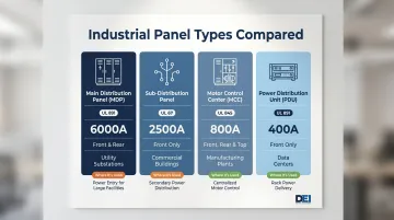
- Panel types — MDPs, sub-distribution panels, MCCs, and PDUs — serve different distribution tiers; choosing the right one depends on load, location, and application
- UL-certified components and routine maintenance are what keep a panel performing reliably across its 30–40 year service life
What Is an Industrial Power Distribution Panel?
An industrial power distribution panel is an enclosed assembly that receives high-capacity electrical power from a utility source or transformer and divides it into multiple controlled circuits for distribution throughout a facility. Unlike residential panels—which typically handle 200 amps and simple single-phase loads—industrial panels manage 400 to 5,000 amps, three-phase power, and fault current ratings up to 200,000 AIC. This scale difference demands entirely different construction and protection standards.
The panel solves a specific operational problem: without a centralized distribution point, facilities can't isolate faults, balance loads across circuits, or shut down one equipment zone without cutting power site-wide.
It's not a passive splitter. It's an active protection and control system that continuously monitors current flow, detects faults, and isolates problems before they cascade.
What an industrial power distribution panel is not:
- Not a transformer (which changes voltage levels)
- Not a generator (which produces power)
- Not a motor control center (though MCCs are often integrated alongside distribution panels)
The architecture of these panels has stayed consistent for good reason: the core job hasn't changed. What has evolved is the sophistication of the protection components inside — the breakers, busbars, metering, and controls that determine how reliably a facility operates under load.
Key Components of an Industrial Power Distribution Panel and Their Functions
Every component inside a power distribution panel has a defined job. Knowing what each part does—and why it's sized or rated the way it is—drives better specification decisions, faster troubleshooting, and more effective maintenance.
Power Input and Distribution Components
Main Breaker
The main breaker is the primary disconnect for the entire panel. It provides overcurrent protection at the highest ampacity level in the system—typically 400 to 4,000 amps in industrial applications—and serves as the first line of defense against catastrophic faults. Industrial main breakers differ from residential units in several ways:
- Adjustable trip settings allow fine-tuning of overload and short-circuit protection
- Ground fault protection detects leakage currents that could cause fires or equipment damage
- 100% continuous rating on breakers with 250A or larger frame sizes (residential breakers are typically rated at 80% continuous)
Main breakers must be rated to interrupt the maximum available fault current at the installation point. Per UL 489 standards, breakers with frame sizes from 1,600A to 6,000A are available for the largest industrial systems.
Bus Bars
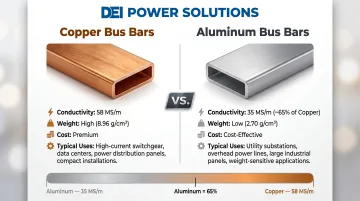
Bus bars are the panel's internal power highway—heavy-duty copper or aluminum conductors that carry current from the main breaker to each branch circuit position. Industrial panels use oversized bus bars rated for continuous full-capacity operation, often with silver-plated or tin-plated connections to reduce resistance and resist corrosion over decades of use.
Copper bus bars offer approximately 58 MS/m conductivity, while aluminum provides about 35 MS/m (roughly 65% of copper's value). The choice between materials depends on ampacity requirements, weight constraints, and cost considerations. According to Eaton specifications, motor control centers use tin-plated copper bus bars as standard, with silver-plated copper available for horizontal bus connections.
Protection and Circuit Management Components
Branch Circuit Breakers
Branch circuit breakers protect individual loads or zones. Each breaker monitors current on its circuit and trips when a fault or overload is detected, isolating only the affected circuit rather than shutting down the entire panel. Modern industrial breakers support selective coordination—a critical design feature that minimizes the blast radius of any single fault.
Two primary trip mechanisms exist:
| Feature | Thermal-Magnetic | Electronic (Solid-State) |
|---|---|---|
| Overload mechanism | Bimetallic strip (heat-based, time-delayed) | Current transformers + microprocessor |
| Short-circuit mechanism | Electromagnetic coil (instantaneous) | Digital processing with programmable delay |
| Adjustability | Fixed or narrow range | Wide range: Long Time, Short Time, Instantaneous, Ground |
| Ambient sensitivity | Affected by temperature changes | Not affected by ambient temperature |
| Typical applications | Sub-distribution, lighting, simple motor feeders | Main distribution boards, critical power |
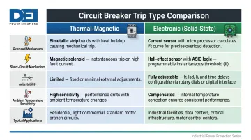
Electronic trip units enable precise coordination between upstream and downstream breakers, preventing nuisance trips and ensuring that only the faulted circuit is isolated.
Surge Protection Devices (SPDs)
SPDs defend the panel against transient voltage spikes from lightning, utility switching events, or large motor starts. They are especially critical in industrial environments where PLCs, variable frequency drives, and sensitive electronic controls are present.
The NEC 2023 edition expanded SPD requirements significantly:
- Section 409.70: Industrial control panel safety circuits subject to surge damage must have SPDs
- Section 695.15: Listed SPD required in/on fire pump controller
- Section 700.8: Listed SPD required on all emergency system switchboards and panelboards
- Section 708.20(D): SPDs required at all facility distribution voltage levels for critical operations
Industrial facilities average 8.3 power quality events per year according to EPRI research. Between expanding code requirements and that event frequency, SPD integration is a specification baseline for any industrial panel today.
Monitoring, Grounding, and Enclosure
Neutral and Ground Bars
The neutral bar provides a return path for current under normal operating conditions, while the ground bar creates a low-impedance fault path that ensures protective devices trip quickly when a ground fault occurs.
In industrial environments with VFDs and non-linear loads, these bars must be sized to handle harmonic currents that exceed fundamental load. Per IEEE 519-2014/2022 standards, systems at 1.0 kV or below must maintain:
- Voltage THD: Maximum 8.0%
- Individual harmonic: Maximum 5.0%
Staying within those limits matters especially in facilities with heavy single-phase non-linear loads. Triplen harmonics (3rd, 9th, 15th) add algebraically in the neutral conductor rather than canceling out—which can push neutral current above phase current and overstress an undersized bar.
Metering Equipment
Digital meters provide real-time visibility into panel performance. Advanced panels go beyond basic monitoring with power quality meters that flag problems before they affect production. Common capabilities include:
- Real-time voltage, current, and power factor readings
- Harmonic and voltage sag detection
- SCADA and building management system integration
- Energy consumption data for predictive maintenance and optimization
Panel Enclosure
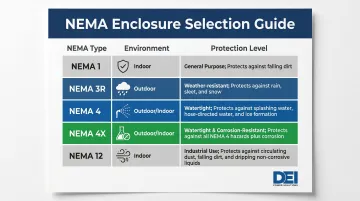
The enclosure serves as both a physical protection barrier and a code compliance element. Industrial enclosures are rated per NEMA standards for specific environmental conditions:
| NEMA Type | Environment | Protects Against |
|---|---|---|
| 1 | Indoor, clean spaces | Falling dirt, accidental contact with live parts |
| 3R | Outdoor | Falling rain, sleet, snow, external ice formation |
| 4 | Indoor/outdoor industrial | Dust, falling dirt, hose-directed water |
| 4X | Indoor/outdoor, corrosive | All NEMA 4 protections plus corrosion resistance |
| 12 | Indoor industrial | Settling dust, falling dirt, oil and coolant splashes |
Enclosure selection is frequently mismatched in industrial panel specification. Using a NEMA 12 enclosure where direct hose spray occurs will result in moisture ingress and component failure. A single unsealed hole or lower-rated accessory downgrades the entire system rating.
How Power Flows Through an Industrial Distribution Panel
Understanding how power moves from input to output allows engineers and technicians to diagnose problems systematically rather than guessing.
Power Entry
Electrical supply arrives from a utility transformer or generator at the main lugs or main breaker terminals. This is where the panel's highest voltage and current levels exist. The main breaker samples incoming current continuously and will trip if current exceeds its set threshold, disconnecting all downstream circuits simultaneously.
Short-circuit current rating (SCCR) becomes critical at this stage. Per NEC Article 409, a panel cannot be installed where available fault current exceeds its marked SCCR. The panel must be rated to safely interrupt the maximum available fault current at the installation point—ratings typically range from 10,000 to 200,000 amperes.
Distribution Across Bus Bars
Power moves from the main breaker to the bus bars, then to each branch circuit position. The bus bars act as a shared conductor that all branch breakers tap into simultaneously.
Load balancing across phases occurs at this stage. Three-phase power can transmit three times as much power as single-phase using only one additional conductor, with AC signals 120 electrical degrees apart providing consistent power delivery.
Unbalanced loading across phases is a common cause of neutral conductor overheating and bus bar degradation.
Protection and Circuit Isolation
Each branch circuit breaker monitors its individual circuit. The breaker measures current flow continuously and uses either a thermal-magnetic or electronic trip mechanism to open the circuit when overload or short-circuit conditions are detected.
Understanding the trip type matters when a breaker keeps tripping:
- Overload trips occur gradually as heat builds in the thermal element — repeated trips suggest undersized conductors or excessive load
- Short-circuit trips trigger instantaneously via magnetic response — indicating a fault condition that requires immediate investigation
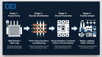
Output to Facility Loads
Conditioned, protected power exits the panel via branch circuit conductors to motors, lighting, HVAC, control systems, and other loads. What arrives at those loads matters as much as whether it arrives — voltage stability, phase balance, and harmonic distortion all affect equipment longevity and uptime. Metering and power quality monitoring instruments give facility teams the data to catch problems before they cause failures.
Types of Industrial Power Distribution Panels and Where They're Used
Different panel types serve different load requirements and facility configurations:
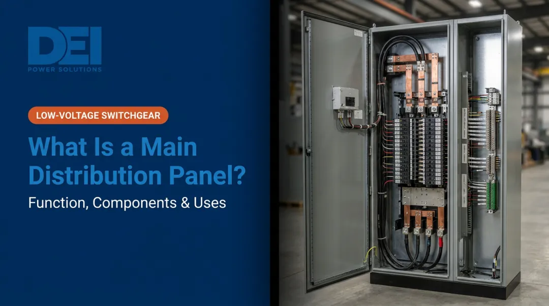
Main Distribution Panels (MDPs)
MDPs serve as the facility-level power hub, receiving utility power and feeding sub-panels. Governed by UL 891 standards, switchboards can accommodate up to 5,000 amps and are freestanding assemblies with front and rear access. They include comprehensive protection features and are typically located in main electrical rooms.
Sub-Distribution Panels
Sub-distribution panels receive power from the MDP and distribute it to specific departments or process areas. Governed by UL 67, panelboards are limited to 1,200 amps maximum per NEC Article 408. They are wall-mounted with front access only and allow localized control, reducing voltage drop on long cable runs and enabling area-specific shutdowns without affecting the rest of the facility.
Motor Control Centers (MCCs)
MCCs combine distribution with motor starting and control functions in a modular assembly. Governed by UL 845 standards, MCCs support up to 3,200A horizontal bus ratings with short-circuit current ratings of 65,000A rms symmetrical at 480V. They house motor starters, VFDs, and feeder taps in plug-in units, allowing easy reconfiguration as production needs change.
Power Distribution Units (PDUs)
PDUs are used in data centers and critical facilities for redundant, monitored distribution. They provide granular circuit-level monitoring and control, often with remote management capabilities. PDUs typically meet UL 891 standards and are designed for rack-mounted or raised-floor installation.
Common Industrial Environments
Industrial power distribution panels are deployed across diverse industries:
- Manufacturing and processing plants with continuous high-load operations
- Data centers and colocation facilities requiring redundant feeds and granular circuit monitoring
- Healthcare facilities where power reliability directly affects patient safety
- Utility substations and infrastructure projects requiring high fault current ratings
- Commercial campuses with complex multi-building distribution needs
Environmental conditions drive enclosure and component specification more than almost any other factor. Washdown requirements in food processing demand NEMA 4X enclosures. Explosion-proof ratings are mandatory in chemical plants. Selecting the wrong panel type or enclosure for an application is a common and costly mistake.
UL Certification and Code Compliance
Panels used in industrial applications must meet standards including UL 891 for switchboards, NEC Article 408, and NFPA 70E. UL 891 certification verifies that equipment has been independently tested for dielectric strength, temperature rise, and fault current interruption capacity. It is a baseline requirement for commercial and industrial installations and is often mandated by inspectors and project specifications.
Key compliance considerations when specifying switchboards:
- UL 891 — required for switchboards; verifies dielectric strength, temperature rise, and fault interruption capacity
- NEC Article 408 — governs panelboard ratings and installation requirements
- NFPA 70E — establishes arc flash and electrical safety standards for industrial environments
For projects where these standards are non-negotiable, DEI Power manufactures UL 891-certified low-voltage switchboards from 400A to 4000A at their Ontario, California facility — with custom configurations for voltage, layout, and load requirements, and in-house engineering support to keep schedules on track.
Conclusion
An industrial power distribution panel is a purpose-built system controlling how power enters a facility, how it is divided and protected, and how it reaches every connected load. Understanding its components and operating sequence gives engineers, contractors, and facility teams a practical foundation for better decisions at every stage—from specification and procurement through maintenance and troubleshooting.
Panels that are correctly specified, properly certified, and regularly maintained form the backbone of reliable operations. Poorly understood or under-maintained panels are consistently among the leading causes of unplanned downtime. Given that industrial facilities face an average of 3.9 outages per year at an average cost of $7,795 per one-hour event, the financial case for getting panel design and maintenance right is clear.
That cost exposure is exactly what sound panel specification is designed to prevent. For contractors and engineers working on time-sensitive projects, DEI Power offers custom UL 891-certified switchboard solutions built to project-specific requirements, including:
- NEMA 1 and NEMA 3R enclosure configurations
- Genuine Siemens components throughout
- Fast lead times with in-house manufacturing
- Comprehensive engineering support from specification through delivery
Contact DEI Power at (866) 773-8050 to discuss your project requirements.
Frequently Asked Questions
What are industrial power distribution components?
Core components include the main breaker (primary disconnect and overcurrent protection), bus bars (internal power conductors), branch circuit breakers (individual circuit protection), neutral/ground bars (safety infrastructure), surge protection devices (transient voltage defense), metering equipment (power monitoring), and the panel enclosure (environmental protection). Each serves a distinct protective or operational function within the distribution system.
What is the difference between a switchboard and a power distribution panel?
Switchboards (governed by UL 891) are larger, freestanding assemblies designed for higher ampacity (up to 5,000A) and more complex configurations with front and rear access. Panelboards (governed by UL 67) are typically wall-mounted, limited to 1,200A maximum, and serve lower-current branch circuit distribution with front access only. Both are types of power distribution equipment but are specified for different load scales and access requirements.
What does UL 891 certification mean for a power distribution panel?
UL 891 is the safety standard for switchboards, verifying independent testing for dielectric strength, temperature rise, and fault current interruption capacity—confirming the equipment can safely handle its rated voltage and current under normal and fault conditions. It is a baseline requirement for commercial and industrial switchboard installations in the U.S. and is typically mandated by inspectors, authorities having jurisdiction, and project specifications.
How do you determine the right size for an industrial power distribution panel?
Panel sizing starts with a full load analysis: calculate running loads and inrush currents, apply diversity factors, and build in at least 25% spare capacity for future growth. Short-circuit current rating (SCCR) must also match the available fault current at the installation point to ensure safe fault interruption.
What is the difference between a main distribution panel and a sub-panel?
An MDP receives power directly from the utility transformer and serves as the facility's primary distribution point, while sub-panels receive power from the MDP and distribute it to specific areas or processes. Sub-panels enable localized control, reduce voltage drop on long runs, and allow area-specific shutdowns without disrupting the rest of the facility.
How often should industrial power distribution panels be inspected and maintained?
NFPA 70B-2023 (now a mandatory standard) recommends monthly visual inspections, quarterly connection checks, and annual comprehensive maintenance including infrared thermal imaging—semi-annually for harsh or critical environments. Connection failures from thermal cycling and moisture ingress are the most common causes of panel degradation, and both are largely preventable with consistent maintenance.