Introduction
The form of separation in LV switchgear determines whether a technician can safely perform maintenance while adjacent circuits stay live — and whether a fault in one compartment shuts down an entire facility or stays contained. In mission-critical environments like data centers, hospitals, and continuous manufacturing plants, that decision directly impacts both personnel safety and operational continuity.
The cost of getting it wrong runs in both directions. Specifying too low a form adds personnel risk and operational vulnerability; specifying unnecessarily high drives up cost, footprint, and lead time. According to the Ponemon Institute, unplanned data center outages cost an average of $8,851 per minute, with power distribution failures accounting for 25% of events.
The right choice requires matching the separation form to the application, personnel competency, and uptime requirements.
Key Takeaways
- Form of separation defines how busbars, functional units, and cable terminals are physically isolated inside LV switchgear
- Four main forms (Form 1–4) with subcategories (2a/2b, 3a/3b, 4a/4b) offer progressively higher protection
- Selection depends on live-access requirements, personnel competency, application criticality, and total cost of ownership
- Form 1 suits low-risk environments; Form 3 or 4 is essential for facilities where uptime is critical
- Always confirm form selection with your switchgear manufacturer before finalizing the design
What Is a Form of Separation in LV Switchgear?
Form of separation defines the type of internal subdivision provided within a low-voltage switchboard, achieved through metallic or non-metallic barriers or partitions that physically isolate three key zones inside the enclosure. Per IEC 61439, these zones are:
The three internal zones:
- Busbars — the main current-carrying conductors that distribute power throughout the assembly
- Functional units — circuit breakers, motor starters, or other devices fulfilling a single electrical function (e.g., outgoing feeders, VSD compartments)
- Terminals for external conductors — connection points where incoming and outgoing cables land
Core Protection Objectives
IEC 61439-1 Clause 8.4 defines two core safety objectives that any form of separation must satisfy:
- IPXXB protection: Prevents direct finger contact with live parts in adjacent compartments when any cover or door used for normal access is opened
- IP2X protection: Prevents solid foreign bodies larger than 12.5 mm from passing between compartments, limiting arc propagation risk
Both thresholds apply during normal maintenance access — and which form your switchboard uses determines how effectively those thresholds hold when things go wrong. That's where the four form levels come in.
The Four Forms of Separation Explained
Each form of separation adds a distinct layer of internal isolation — and the form you specify directly determines what maintenance work can be done safely while the board remains live.
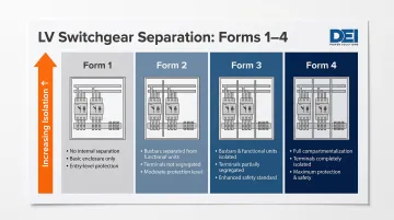
Form 1 — No Internal Separation
Form 1 provides no barriers or partitions between busbars, functional units, or terminals. All internal components are open and accessible within a single compartment.
Appropriate for:
- Small, low-power switchboards in controlled-access environments
- Locations where the entire board can be de-energized for all maintenance
- Low-risk tertiary distribution where personnel access is infrequent
Form 1 is the simplest and least expensive configuration, but offers minimal protection during live work.
Form 2 — Busbar Separation from Functional Units
Form 2 physically separates busbars from functional units. The internationally recognized IEC 61439-2 standard defines two busbar separation methods:
- Type 1: Insulated coverings (sleeving, wrapping, or coatings) separate busbars from functional units
- Type 2: Rigid metallic or non-metallic barriers separate busbars from functional units
Subcategories:
- Form 2a: Cable terminals are not separated from busbars
- Form 2b: Cable terminals are separated from busbars
Form 2 is common in wall-mounted switchgear where baseline protection is needed without full compartmentalization. However, functional units remain in a shared space, so a fault in one unit can affect adjacent units.
Form 3 — Functional Units Separated from Each Other
Form 3 directly addresses that fault propagation risk. It combines Form 2 busbar separation with individual compartments for each functional unit, isolating each outgoing circuit from adjacent circuits.
Subcategories:
- Form 3a: Terminals are not separated from busbars
- Form 3b: Terminals are separated from busbars
A fault or maintenance action in one functional unit does not affect adjacent units. This makes Form 3 practical for facilities where partial maintenance must occur without a full shutdown — industrial motor control centers, process plants, and commercial distribution boards serving critical loads.
Form 4 — Full Separation Including Terminals
Form 4 is the highest protection level: Form 3 plus full isolation of each functional unit's cable terminals from those of all other functional units.
Subcategories:
- Form 4a: Terminals are located in the same compartment as the associated functional unit
- Form 4b: Terminals are housed in a separate enclosed space or compartment, outside the functional unit's compartment
Form 4 enables engineers to work safely on one circuit's terminations while the rest of the switchboard remains live. This level of isolation is essential in high-uptime environments like hospitals, data centers, and continuous industrial processes. The tradeoff is higher cost and a larger footprint due to additional compartmentalization.
Key Factors to Consider When Choosing a Form of Separation
Form of separation isn't a one-size-fits-all specification. The right choice depends on who accesses the equipment, how often, under what conditions, and what a failure or unplanned outage actually costs. Getting this wrong in either direction — specifying too low a form or over-engineering for a non-critical application — creates real financial and safety consequences.
Personnel Access and Competency
The most critical factor is whether personnel need to access the switchgear — or work adjacent to live parts — while other sections remain energized. The higher the probability of live access, the higher the required form.
IEC 61439 guidance links form selection to the competence of the person undertaking work whilst the remainder of the assembly is energised. A less-controlled environment with varying personnel skill levels demands a higher form.
Key questions to ask:
- Will technicians need to isolate one circuit while adjacent circuits remain live?
- Are personnel qualified and trained for energized work (per NFPA 70E or equivalent)?
- Is live work unavoidable due to operational continuity requirements?
If unqualified personnel or contractors will access the switchboard, or if the facility cannot tolerate full de-energization for routine maintenance, Form 3 or Form 4 is required.
Maintenance Requirements and Operational Continuity
Facilities requiring hot maintenance (replacing or servicing a component without de-energizing the full board) need Form 3 or Form 4.
In mission-critical environments, unplanned downtime is extremely costly. According to the Ponemon Institute's 2016 study, the average cost of an unplanned data center outage is $8,851 per minute ($740,357 average total per incident), and the Uptime Institute reports that over 60% of outages now cost at least $100,000.
Applications requiring Form 3 or Form 4:
- Data centers and colocation facilities
- Hospitals and healthcare infrastructure
- Continuous manufacturing and process plants
- Utility substations and critical infrastructure
Lower forms (Form 1 or Form 2) may be acceptable for secondary distribution serving non-critical loads where the entire board can be shut down for planned maintenance without operational impact.
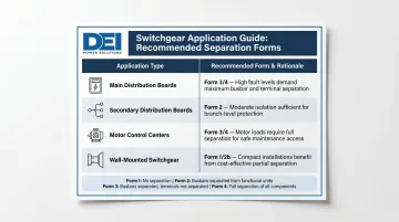
Application Type and Switchgear Role
The role of the switchgear within the system influences form selection:
| Switchgear Type | Typical Form | Reason |
|---|---|---|
| Main distribution boards (MDBs) | Form 3 or Form 4 | High fault energy; directly downstream of transformers |
| Secondary distribution boards | Form 2 or lower | Serve zone loads; less frequent access |
| Motor control centers (MCCs) | Form 3 or Form 4 | Individual starters must be serviceable without shutting down the line |
| Wall-mounted switchgear | Form 1 or Form 2b | Low-risk tertiary applications with infrequent access |
Physical Space and Enclosure Size
Higher forms require more internal barriers, partitions, and compartmentalization, which increases the physical footprint of the switchgear enclosure. This is a practical constraint in retrofit or space-limited projects.
The BEAMA Guide puts it plainly:
"The higher the degree of separation, the larger the assembly. Barriers and partitions take up space [and] may restrict air flow necessitating the use of larger components to achieve the required rating."
Practical implications:
- Internal partitions reduce heat dissipation, potentially requiring conductor derating or larger components
- Form 4b assemblies require more enclosure width and depth than Form 1 or Form 2
- Specifiers must account for ventilation, cable entry space, and access clearances
Budget and Total Cost of Ownership
Form 1 costs the least upfront but provides minimal protection and may require full de-energization for any maintenance work, increasing operational downtime costs over time.
Higher forms (Form 3 or Form 4) have higher initial material and labor costs due to additional barriers, partitions, and larger enclosures. However, they reduce the financial risk of unplanned outages.
Total cost of ownership (TCO) considerations:
- A $20,000 cost premium for Form 4 vs. Form 2 is easily justified if it prevents even one $740,000 unplanned outage over the switchgear's 20-year life
- In low-criticality applications where downtime carries minimal cost, Form 1 or Form 2 typically offers better TCO
- Factor in maintenance labor, component sizing, and enclosure footprint — not just the unit price
How DEI Power Helps You Specify and Build the Right Switchgear
DEI Power has over ten years of experience building UL 891-certified LV switchboards for commercial, industrial, utility, and data center applications. Because form of separation is negotiated between manufacturer and end user, your specification choices directly affect safety, layout, and cost — which means the manufacturer you work with needs to understand the technical tradeoffs before manufacturing begins.
Engineering-Backed Specification Support
DEI Power's in-house engineering team helps contractors and facility teams translate application requirements into correct specifications before manufacturing begins:
- Pre-sales consultation to review project requirements and align compliance needs
- Specification review to verify ratings, enclosure selection, and system configuration
- Drawing submission with detailed electro-mechanical schematics and CAD layouts
- Formal configuration review to ensure code compliance and practical execution
This front-end process reduces costly change orders and field adjustments before a single component is assembled.
Custom Switchgear Capability
DEI Power builds switchgear to customer specs, including:
- Voltage ratings (120/240V, 208Y/120V, 480V, 480Y/277V)
- Amperage range (400A–4000A)
- NEMA 1 (indoor) or NEMA 3R (outdoor) enclosures
- Custom layouts and busbar configurations
As an Approved Siemens OEM, DEI Power integrates Siemens components that meet UL 891 compliance requirements out of the box.
Key Differentiators for Specifiers
- UL 891-certified switchboards manufactured in the USA (50,000 sq. ft. facility in Ontario, CA)
- 3–5 business day lead times for in-stock units; 4–6 weeks for custom builds
- BABA-compliant construction for federally funded public infrastructure projects
- Free shipping on all orders
- Clear documentation including submittals, UL certification, wiring diagrams, and compliance support
To discuss form of separation requirements or get a specification review for your project, contact DEI Power at (866) 773-8050 or sales@deipower.com.
Frequently Asked Questions
What is the difference between Form 3 and Form 4 separation in LV switchgear?
Form 3 separates busbars from functional units and separates functional units from each other. Form 4 adds full isolation of each functional unit's cable terminals from those of all other functional units, making it the choice when live termination access is required.
What is the difference between Form 4a and Form 4b?
In Form 4a, the cable terminals are located within the same compartment as the associated functional unit. In Form 4b, the terminals are housed in a separate, individually enclosed space outside the functional unit's compartment, providing an additional layer of isolation for high-risk environments.
Which form of separation is typically used for main distribution boards?
Form 3 or Form 4 is most commonly specified for main distribution boards due to their high fault energy levels and the operational requirement to access or maintain one circuit without de-energizing the full board.
Does a higher form of separation increase switchgear size and cost?
Yes: each additional level of internal separation requires more partitions, barriers, and enclosure space, which increases both material costs and physical footprint. Engineers and project teams should evaluate this against the total cost of ownership including downtime risk.
What IP protection level is required inside separated compartments per IEC 61439?
IEC 61439 requires at least IPXXB protection against direct contact with live parts in adjacent compartments, and at least IP2X against solid foreign body ingress — both enforced when any cover or door used for normal access is opened or removed.
Can different sections of the same installation use different forms of separation?
Yes. Different switchboards within the same installation can be specified to different forms of separation based on their individual access requirements, fault risk levels, and operational roles — a common practice agreed between manufacturer and end user.