When a fault occurs — an overload, short circuit, or ground fault — switchgear detects the problem, isolates the affected section, and keeps the rest of the system energized. This capability matters because 54% of data center outages cost more than $100,000, with power-related problems causing approximately 44% of significant outages. In hospitals, downtime averages $7,500 per minute.
This guide covers what switchgear is, how it works, the main types by voltage and insulation medium, key components, and where it's deployed — giving you the working knowledge to specify, evaluate, and maintain this equipment confidently.
Key Takeaways
- Switchgear is a centralized assembly of circuit breakers, fuses, and switches that controls, protects, and isolates electrical equipment
- Detects faults and interrupts power to affected sections while keeping the rest of the system live
- Classified by voltage level (low, medium, high) and insulation type (air, gas, oil, or vacuum)
- Built around circuit breakers, disconnect switches, protective relays, and fuses
- Used in commercial buildings, data centers, industrial plants, healthcare facilities, and utility substations
What Is Electrical Switchgear?
Electrical switchgear is a centralized collection of circuit protection and switching devices — including circuit breakers, fuses, and disconnect switches — mounted together in a common metal enclosure to control, protect, and isolate electrical equipment within a power distribution system.
IEEE C37.100-1992 formally defines switchgear as equipment "for switching, interrupting, metering, protection, and regulating purposes as used primarily in connection with generation, transmission, distribution, and conversion of electric power."
Two Core Component Categories
Every switchgear assembly contains:
- Power-conducting components — Switches, circuit breakers, and fuses that carry or interrupt electrical current
- Control and monitoring components — Protective relays, control panels, and current transformers that detect abnormal conditions and trigger protective responses
Switchgear vs. Switchboard: What's the Difference?
These terms are often used interchangeably, but they serve different purposes:
| Attribute | Switchgear | Switchboard (UL 891) |
|---|---|---|
| Voltage range | Low, medium, and high voltage (up to 350 kV+) | 600V or less |
| Short-circuit test | 15% power for 30 cycles (unfused) | 20% power for 3 cycles |
| Construction | Circuit breakers in individual metal compartments | Panels for redirecting/distributing power |
| Primary function | Fault identification and power interruption | Power distribution |
Switchgear typically refers to higher-complexity assemblies with greater fault interrupting capacity and component separation (such as metal-clad designs). Switchboards are distribution-focused panels used in lower-voltage, less demanding settings.
DEI Power manufactures UL 891-certified low-voltage switchboards in the 400A–4000A range for commercial, industrial, and utility applications.
Which type applies to your project depends largely on the applicable governing standard.
Governing Standards
In North America:
- IEEE C37.20.2 for metal-clad switchgear
- UL 891 for low-voltage switchboards
- ANSI standards for construction and safety
In Europe and most of the world:
- IEC 62271-200 for metal-enclosed switchgear
- IEC 62271-100 for high-voltage AC circuit breakers
Compliance with these standards determines whether equipment is code-acceptable on your project.
How Does Electrical Switchgear Work?
Switchgear operates in two primary modes: normal operation and fault response.
Normal Operating State
Under regular conditions, switchgear allows current to pass unimpeded, distributing power from a source — utility feed, generator, or transformer — to downstream loads throughout a facility. Circuits, panels, and equipment receive stable power with no interruption.
What Happens During a Fault
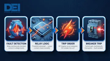
When a fault condition occurs (overcurrent, short circuit, ground fault), the sequence unfolds as follows:
- Fault detection: Protective relays monitor current and voltage via Current Transformers (CTs) and Voltage Transformers (VTs). Per IEEE Region 5 documentation, microprocessor relays sample analog signals, convert them to digital values, and calculate phasors against set thresholds.
- Relay logic: When thresholds are exceeded, the relay closes a physical output contact.
- Trip order: This contact completes the DC tripping circuit, energizing the circuit breaker's trip coil.
- Breaker trip: The breaker mechanically interrupts the current path, isolating the fault.
Fault type distribution in industrial and commercial systems:
- Single-phase-to-ground faults: 70–80%
- Phase-to-phase-to-ground: 10–17%
- Phase-to-phase: 8–10%
- Three-phase: 2–3%
Fault Isolation: The Key Operational Advantage
Switchgear isolates a faulted section — cutting power to the problem area — while keeping the rest of the system energized. In hospitals, data centers, and industrial plants, that distinction matters: a localized trip keeps operations running; a full shutdown doesn't.
Maintenance Isolation Function
Fault response is reactive. Maintenance isolation is the planned counterpart. Disconnect switches allow technicians to de-energize specific equipment for safe inspection, testing, or repair — without shutting down the entire power system.
Arc Flash as a Safety Consideration
When contacts open under load, an electrical arc can form. Arc temperatures can reach 35,000°F, and copper vapor expands by 67,000 times. Arc-resistant switchgear (tested to ANSI/IEEE C37.20.7) is designed to vent arc energy through controlled exhaust paths — directing the blast away from the front panel, where personnel typically stand.
IEEE C37.20.7 Accessibility Types:
| Type | Protection Scope |
|---|---|
| Type 1 | Arc-resistant at the front of the equipment only |
| Type 2 | Arc-resistant around the entire perimeter |
| Type 2B | Entire perimeter, even with instrument/control compartment doors open |
| Type 2C | Protection between adjacent compartments (MV metal-clad only) |
The preferred arcing duration test rating is 0.5 seconds.
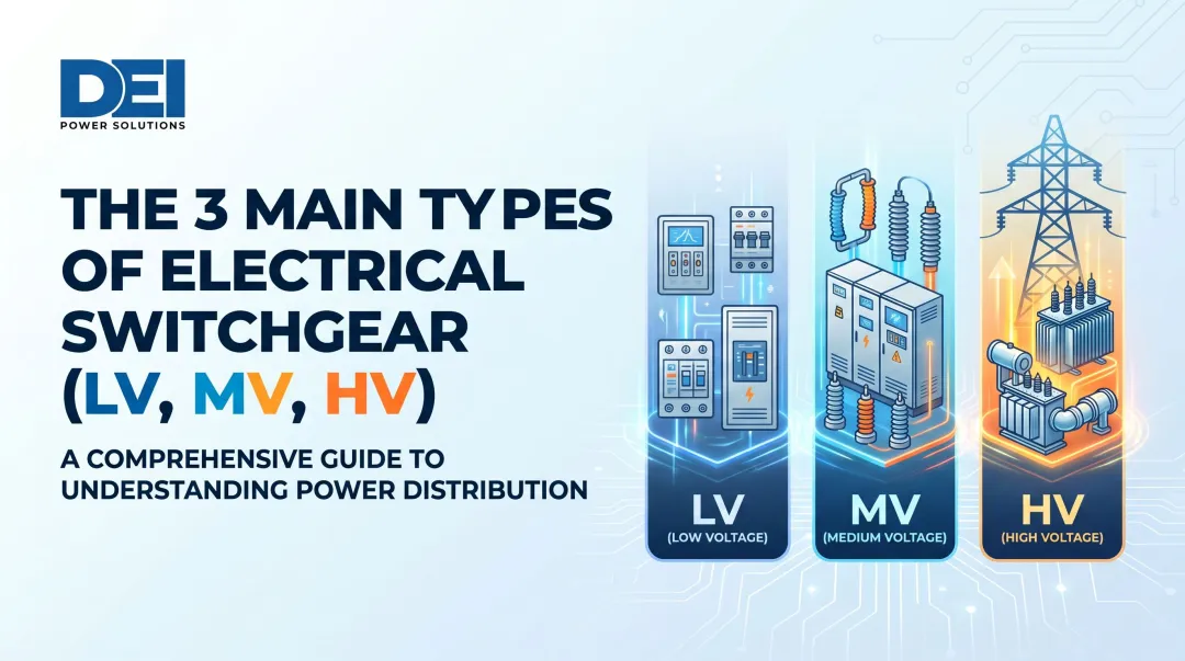
Types of Electrical Switchgear by Voltage Level
Voltage classification is the starting point for any switchgear selection decision. Using equipment rated below the system voltage isn't just a performance issue — it's a code violation and a safety hazard.
Low-Voltage (LV) Switchgear
LV switchgear covers equipment rated up to 1,000V AC under NEC 2014 — a threshold raised from 600V to accommodate alternative energy systems that operate above the old limit. Older ANSI definitions still reference 600V, so the applicable standard matters when specifying equipment.
This is the most widely deployed voltage class, found in commercial buildings, data centers, light industrial facilities, and campuses where building-level power distribution is the primary need.
UL 891 is the governing certification for LV switchboards in the U.S., covering construction, performance, and safety. Annex G of the standard allows ratings up to 4,000A (US) / 3,000A (Canada) with short-circuit ratings up to 100 kA. DEI Power manufactures UL 891-certified switchboards built with Siemens components in configurations from 400A to 4,000A, available for commercial, industrial, and utility projects nationwide.
Medium-Voltage (MV) Switchgear
MV switchgear operates between 1 kV and approximately 35–38 kV, serving utility distribution systems, large industrial plants, campuses with on-site substations, and utility grid connection points where incoming service voltage exceeds what LV equipment can handle.
Construction type is one of the key differentiators at this voltage class:
- Metal-clad (IEEE C37.20.2) — fully compartmentalized, highest level of maintenance isolation
- Metal-enclosed (IEEE C37.20.3) — compartmentalized but less rigidly defined than metal-clad
- Pad-mounted — compact, ground-level units common in underground distribution systems
- Compact/GIS variants — gas-insulated switchgear for space-constrained or high-reliability environments
Each type trades off compartmentalization, maintenance access, and footprint differently depending on the application.
High-Voltage (HV) Switchgear
HV switchgear covers equipment rated above 35 kV, though some standards set the threshold at 69 kV. It's used in transmission networks, large power generation facilities, and major utility substations — anywhere electricity needs to be switched or protected across long-distance, high-voltage infrastructure.
At this level, equipment selection, installation, and maintenance are governed by utility-grade standards and typically handled by specialized engineering teams.
Types of Switchgear by Insulation Medium
The insulation medium — the material or environment surrounding energized components — determines dielectric strength (the ability to resist electrical breakdown), equipment footprint, maintenance requirements, and environmental suitability.
Here's how the main types compare at a glance:
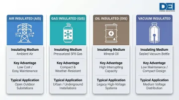
| Type | Insulating Medium | Key Advantage | Typical Application |
|---|---|---|---|
| Air (AIS) | Ambient air | Low cost, easy maintenance | Open substations, MV/HV with available space |
| Gas (GIS) | Pressurized SF6 | Compact, weather-resistant | Urban substations, underground installations |
| Oil (OIS) | Mineral oil | High interrupting capacity | Legacy HV applications |
| Vacuum | Sealed vacuum bottle | Low maintenance, compact | MV distribution, commercial/industrial |
Air-Insulated Switchgear (AIS)
AIS uses ambient air as the primary insulating medium. It's the most widely deployed switchgear type — largely because of its straightforward design, low upfront cost, and ease of maintenance.
The tradeoff is space. AIS requires approximately 1.5 meters of clearance at 145 kV, and its lower dielectric strength makes it more vulnerable to pollution, humidity, and animal intrusion than sealed alternatives.
Best for: MV (3.6 kV–72.5 kV) and HV systems where outdoor space is available and environmental conditions are manageable.
Gas-Insulated Switchgear (GIS)
GIS uses pressurized sulfur hexafluoride (SF6) gas sealed inside metal enclosures. Its significantly higher dielectric strength allows it to occupy just 10–30% of the space required by equivalent AIS — making it the go-to choice for urban substations, underground installations, and any site where footprint is constrained. Lower maintenance requirements also reduce total cost of ownership over time, despite an initial price that runs 1.5–3x higher than AIS.
The major drawback is environmental. SF6 carries a Global Warming Potential of 23,500 times that of CO2 and persists in the atmosphere for over 1,000 years. In 2022, electrical transmission and distribution accounted for roughly 67% of all SF6 emissions in the U.S.
Regulatory pressure is accelerating the transition away from SF6. EU Regulation 2024/573 bans SF6 in new MV switchgear up to 24 kV starting January 1, 2026, and up to 52 kV by 2030. Alternative insulation technologies — including clean air and solid dielectrics — are already entering the market.
Oil-Insulated Switchgear (OIS)
OIS uses mineral oil as both an insulating and cooling medium. Once common in HV transmission applications, it has largely been phased out in new installations due to fire risk and environmental concerns around oil spills and disposal.
Vacuum Switchgear
Vacuum switchgear interrupts arcs inside sealed vacuum bottles, where the absence of conducting medium causes the arc to extinguish rapidly. The result is high dielectric strength, minimal maintenance, and a compact form factor.
It's now the dominant interrupting technology for MV applications. Indoor and panel-mounted vacuum circuit breakers held approximately 40% revenue share of the medium-voltage circuit breaker market in 2025, with widespread use across utilities, industrial plants, and commercial buildings.
Key Components of a Switchgear System
While configurations vary by voltage class and application, all switchgear assemblies share a common set of functional components — circuit breakers, disconnect switches, protective relays, and fuses — each serving a distinct role in controlling and protecting the system.
Circuit Breakers
Circuit breakers are the primary interrupting device in switchgear. They automatically disconnect a circuit when current exceeds a safe threshold, protecting equipment from overloads and short circuits.
Breakers are classified by interrupting medium (air, vacuum, or SF6) and by construction — either fixed or draw-out. The construction type has significant implications for maintenance access and system uptime:
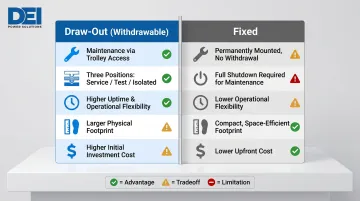
Draw-Out vs. Fixed Circuit Breakers:
| Attribute | Draw-Out (Withdrawable) | Fixed |
|---|---|---|
| Maintenance | Breakers slide out via trolley; three positions (service, test, isolated); no full shutdown needed | Components permanently mounted; typically requires full power shutdown |
| Cost | Higher initial cost | Lower upfront cost |
| Uptime | Minimizes downtime; ideal for data centers and factories | Suitable for simpler, less critical setups |
| Footprint | Larger due to racking mechanism | More compact |
Draw-out designs are referenced in IEEE C37.20.1-2015, which explicitly covers "stationary or drawout, manually or electrically operated low-voltage AC or DC power circuit breakers in individual metal compartments."
Disconnect Switches
Disconnect switches are manually operated devices that physically isolate equipment from the power supply to enable safe maintenance. One critical distinction: they cannot interrupt fault current and must only be operated on de-energized circuits.
Protective Relays
Protective relays continuously measure electrical parameters — voltage, current, frequency — and issue trip signals to circuit breakers when they detect abnormal conditions.
Relay Architectures:
- Electromechanical relays: Include Magnetic Attraction Units (instantaneous) and Induction Disk relays (inverse-time)
- Microprocessor-based relays: Computer-based systems using A/D conversion, digital filtering, and programmable logic
Capabilities of Modern Relays:
- Event reports (typically 15 cycles of data per trip)
- Sequential Events Records (SER) for chronological logic tracking
- Communications ports for remote monitoring
- Programmable timers and logic
Fuses
Fuses are passive overcurrent protection devices that interrupt a circuit by melting when current exceeds a rated level. Simple and reliable, they're commonly paired with load-break switches in medium-voltage switchgear — and frequently used for transformer protection and branch circuit applications where low-cost interruption is sufficient.
Where Is Switchgear Used? Common Applications
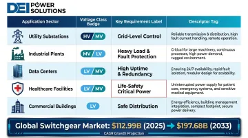
Each application environment has distinct voltage requirements, load profiles, and uptime expectations. The global switchgear market was valued at $112.99 billion in 2025 and is projected to reach $197.68 billion by 2033 at a 7.4% CAGR — a growth rate driven largely by data center expansion, grid modernization, and healthcare infrastructure investment.
| Application | Voltage Class | Key Requirement |
|---|---|---|
| Utility Substations & Transmission Infrastructure | HV/MV | Grid-level power control and distribution |
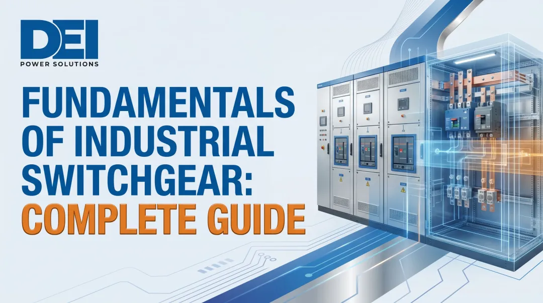
| Large Industrial Plants & Manufacturing | MV/LV | Heavy load management and fault protection |
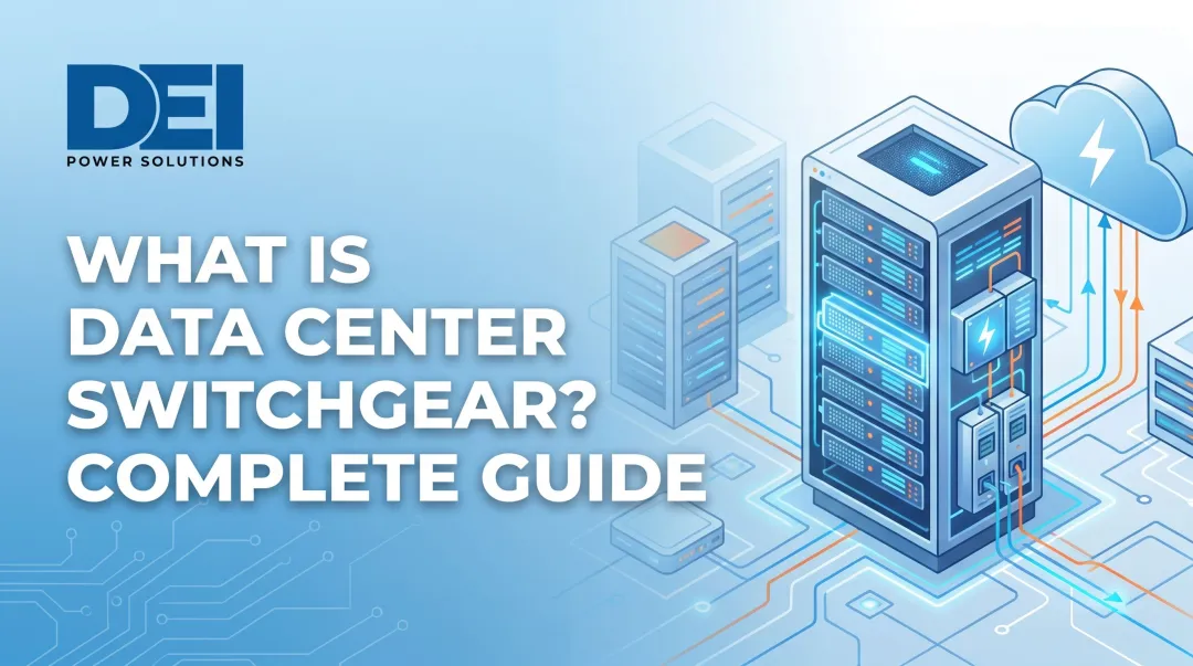
| Data Centers & Colocation Facilities | LV/MV | High uptime and redundant feed capability |
| Healthcare Facilities | LV/MV | Critical power for life-safety systems |
| Commercial Buildings & Campuses | LV | Safe, efficient power distribution |
Hospitals face $1.7–$3.2 million per hour in downtime costs — making reliable switchgear selection a financial and safety priority, not just a code requirement.
Selection Factors
Specifying the right switchgear means matching equipment to your project's actual conditions. Key factors include:
- Voltage level — LV, MV, or HV determines the equipment class and applicable standards
- Fault current rating — short-circuit capacity must meet or exceed available fault current at the installation point
- Environment — indoor vs. outdoor, ambient temperature, humidity, and exposure all affect enclosure and insulation requirements
- Space constraints — footprint and bus configuration affect whether standard or custom builds are needed
- Applicable standards — UL, ANSI, IEC, or NEMA requirements vary by project type and jurisdiction
For low-voltage commercial and industrial applications, DEI Power manufactures UL 891-certified switchgear (400A–4000A) with in-house engineering support and in-stock inventory available in 1–5 business days.
Frequently Asked Questions
What is switchgear and power distribution?
Switchgear is the assembly of protective and switching devices that controls and safeguards an electrical system. Power distribution is the broader network that delivers electricity from a source to end loads. Switchgear is the critical control layer within that distribution system.
What is the difference between GIS and RMU?
GIS (Gas-Insulated Switchgear) is a broad category using SF6 gas for insulation across various voltage levels. An RMU (Ring Main Unit) is a specific type of compact, sealed MV switchgear (often GIS-based) designed for looped distribution networks in urban or space-constrained environments.
What is a DP box?
A DP (Distribution Panel) box is a low-voltage electrical enclosure that receives power from a main switchboard or switchgear assembly and distributes it to individual circuits within a building or facility. It is a downstream component in the power distribution hierarchy, not the same as switchgear.
What is the difference between switchgear and a switchboard?
Switchgear refers to higher-complexity assemblies with greater fault interrupting capacity, individual compartmentalization, and higher-voltage applications. Switchboards are simpler distribution panels for lower-voltage environments, though the terms are sometimes used interchangeably.
What standards apply to low-voltage switchgear in the U.S.?
UL 891 is the primary standard for low-voltage switchboards in the U.S., covering construction, performance, and safety requirements. ANSI and IEEE standards (such as the IEEE C37.20 series) govern broader switchgear classifications, and NEC compliance is required for installation.
How does switchgear protect against arc flash?
Arc-resistant switchgear (tested to ANSI/IEEE C37.20.7) uses reinforced enclosures and pressure-relief plenums to contain and redirect arc flash energy away from personnel. Standard switchgear minimizes arc flash risk through fast fault-clearing times and proper protective relay coordination.