IEC 61439-1 governs certification of LV switchgear assemblies rated ≤ 1000 V AC and defines 13 type tests manufacturers must carry out — divided into 7 core type tests and 6 additional construction quality tests. Understanding these tests helps contractors, engineers, and facility teams evaluate switchgear quality, ask better questions of manufacturers, and reduce the risk of compliance failures or unplanned downtime on critical power distribution projects.
Key Takeaways
- Type tests are pre-market verification tests performed by the manufacturer on a representative assembly to confirm it meets IEC 61439-1 requirements
- IEC 61439-1 defines 13 type tests: 7 cover electrical and mechanical performance; 6 address construction quality and environmental resilience
- One standardized test per design replaces repeated, costly individual verification checks
- For US-based projects, UL 891 certification is the governing standard for low-voltage switchboards
- Assemblies that pass type testing deliver predictable performance, cleaner compliance documentation, and fewer in-field failures
What Are Type Tests for Low Voltage Switchgear?
A type test is a one-time verification performed on a representative prototype of an assembly design — not on every unit produced — to confirm it meets IEC 61439-1 requirements before it is sold or installed. The standard takes this approach because many of these tests are destructive, time-consuming, and too costly to run on every unit.
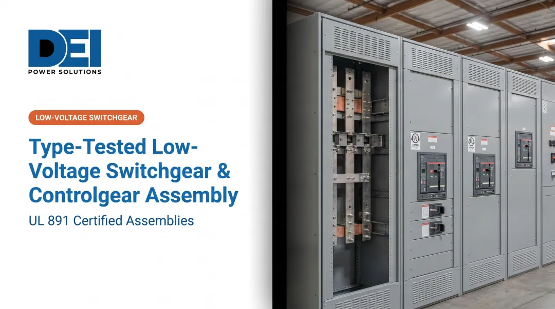
LV switchgear and controlgear assemblies covered by these tests are typically used at three points in an electrical installation:
- LV main switchboard (transformer area)
- LV main distribution board (technical area)
- Sub-distribution boards
Once a design passes type tests, assemblies built to that same design are considered verified. Assemblies built entirely from type-tested layouts are called standard assemblies.
IEC 61439 recognizes three ways a design can be verified — not just physical lab testing:
| Method | Description |
|---|---|
| Laboratory testing | Physical testing on a representative prototype |
| Comparison with reference design | Structured comparison of new design against a tested prototype |
| Assessment/calculation | Use of defined rules, safety margins, or calculations (e.g., IEC 60890 for temperature rise) |
Why Type Tests Matter for Safety and Compliance
Skipping or failing type tests isn't a paperwork problem — it's a safety and liability problem. Unverified assemblies can fail under fault conditions, causing equipment damage, unplanned downtime, and direct risk to personnel.
Real-World Safety Impact:
- NFPA reports 147 occupational fatalities from electricity and arc flash exposure in 2023 alone (averaging 147/year over 2014-2023)
- The average industrial facility loses approximately $125,000 per hour of unplanned downtime
Type tests collectively confirm that the assembly can:
- Handle rated currents without overheating (preventing thermal runaway)
- Withstand fault conditions without structural failure (preventing arc flash hazards)
- Maintain safe insulation (preventing insulation breakdown)
- Protect personnel through effective earthing
US vs. International Standards:
| Attribute | UL 891 (US) | IEC 61439 (International) |
|---|---|---|
| Approach | Prescriptive (specific construction details mandated) | Performance-based (relies on type testing) |
| Max voltage | 600V | 1000V AC |
| Max fault current | 200kA rms | Defined by Icw/Ipk ratings |
| Code alignment | NFPA 70 (US NEC) | International/EU frameworks |
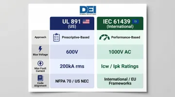
For US-based projects, UL 891 is the governing standard — and certification documentation is what code inspectors and project owners will ask for. DEI Power manufactures UL 891-certified switchboards in Ontario, California, with configurations from 400A to 4000A fully documented for NFPA 70 compliance and ready for submittal packages.
The 7 Core Type Tests Under IEC 61439
Seven core type tests are officially required under IEC 61439-1 for all standard LV assemblies, covering both electrical and mechanical performance verification.
1. Temperature Rise Limits Test
This test loads the incoming circuit and outgoing circuits to their rated current to verify that temperatures across all components — busbars, joints, terminals, cable connections, and internal air — stay within manufacturer-specified limits.
Test Protocol:
- Assembly is loaded until conditions stabilize (typically 8 hours)
- Temperatures monitored via thermocouples at critical points
- Three testing options: testing a specific arrangement, testing circuits individually then together, and modular component-level testing for flexible systems
Maximum Permissible Temperature Rise:
| Component | Max Rise (K) above 35°C ambient |
|---|---|
| Terminals for external insulated conductors | 70 |
| Bare copper busbars/conductors | 105 |
| Manual operating means (metal) | 15 |
| Manual operating means (insulating) | 25 |
| Accessible external metal enclosures | 30 |
| Accessible external insulating enclosures | 40 |
Why This Matters:
Excessive temperatures accelerate insulation aging and component degradation, reducing service life and leading to premature failure. The Arrhenius-based rule states that every 10°C increase in operating temperature approximately halves insulation thermal life. Component ratings assume operation within those thermal boundaries — exceed them and the rated performance figures no longer apply.
2. Dielectric Properties Test
This test applies high voltage at industrial frequency (50 Hz) and in the form of impulse waves simulating a lightning strike to verify that insulation materials can withstand the maximum operating voltage without breakdown.
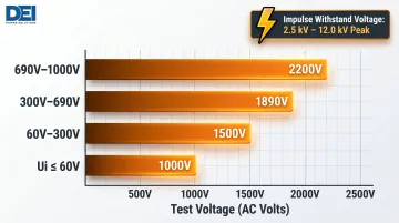
Power-Frequency Withstand Voltage:
| Rated Insulation Voltage (Ui) | Test Voltage (AC) |
|---|---|
| Ui ≤ 60V | 1,000V |
| 60V < Ui ≤ 300V | 1,500V |
| 300V < Ui ≤ 690V | 1,890V |
| 690V < Ui ≤ 1000V | 2,200V |
Impulse Withstand Voltage (1.2/50 microsecond waveform):
Test voltages range from 2.5 kV to 12.0 kV peak depending on the rated impulse withstand voltage (Uimp).
Why This Matters:
Dielectric failure is one of the most dangerous failure modes in LV equipment, potentially causing flashover, arc faults, or destruction of insulation. Research shows that moisture reduces breakdown voltage by more than 50%, making this test critical for confirming the assembly can safely handle voltage surges encountered in real installations.
3. Short-Circuit Resistance Test
This test subjects busbars, their supports, breaking and protection devices, and enclosures to the thermal and electrodynamic stresses produced by short-circuit fault currents.
Key Parameters Verified:
- Icw: Rated short-time withstand current (r.m.s. value; durations of 0.2s, 1s, or 3s)
- Ipk: Rated peak withstand current
- Icc: Rated conditional short-circuit current (with specific protective device)
Why This Matters:
During a fault, extreme electromagnetic forces act on busbars and conductors. An assembly that has not been tested for short-circuit resistance may deform, lose contact integrity, or fail to contain the fault, putting both equipment and personnel at risk. For DEI Power's UL 891-certified switchboards built with Siemens components, short-circuit withstand has been verified through both component-level and system-level testing.
4. Effectiveness of the Protective Circuit Test
This test verifies the continuity of the protective (earthing) circuit by applying a test current of 25 A between the protective conductor terminal and all exposed conductive parts. It also verifies that the protective circuit can withstand the maximum short-circuit thermal stress that could occur at the supply end of the assembly.
Why This Matters:
The protective circuit is the last line of defense against electric shock. If earthing continuity is broken or undersized, fault current may not be cleared quickly enough to protect personnel. 17% of electrical fatalities occur at industrial premises — a number that drops when protective circuits are properly sized, verified, and maintained.
5. Clearances and Creepage Distances Test
This test verifies that the physical distances between live parts of different polarities, and between live parts and exposed conductive parts, meet the minimum values specified in IEC 60664-1.
Critical Areas Checked:
- Connections and terminal blocks
- Conductor bundles
- Busbar separation
- Insulating barriers
Connections and wiring present the greatest risk of reduced insulation values and must be carefully checked.
Why This Matters:
Insufficient clearances or creepage distances can allow flashover or tracking across insulating surfaces, particularly in humid or contaminated environments. Unlike other verification methods, IEC 61439-1 requires this test to be confirmed by laboratory testing only — neither design assessment nor comparison with a reference assembly is an acceptable substitute.
6. Mechanical Operation Test
This test verifies the correct mechanical operation of parts and devices not covered by their own specific component standards, including drawout racks and faceplate fixings, which are tested through 50 operating cycles to confirm reliable movement and engagement.
Why This Matters:
Mechanical failures in drawout components, interlocks, or panel fixings can prevent correct isolation or protection operation. During an unplanned shutdown, a stuck drawout rack or failed interlock can delay isolation — turning a routine fault into an extended outage. This test must be verified by testing only under IEC 61439-1 clause 10.13.
7. Degree of Protection (IP Rating) Test
This test verifies the enclosure's ability to prevent access to hazardous internal parts and to resist the ingress of solid objects and liquids, as defined by the IP code per IEC 60529.
Common IP Ratings:
| IP Rating | Protection Level | Typical Application |
|---|---|---|
| IP20 | Finger protection | Basic indoor installations |
| IP31 | Ingress protection for indoor use | Standard switchboards |
| IP54 | Dust and splash protection | Industrial environments |
| IP65 | Dust tight and water jet protection | Outdoor/harsh environments |
The first digit covers solid/dust ingress (0-6); the second covers liquid ingress (0-9).
Why This Matters:
The IP rating determines where an assembly can be safely installed. An enclosure that fails its IP test may allow dust or moisture to compromise insulation, cause corrosion, or create shock hazards in environments where the rating is critical to safety. DEI Power's switchboards are available in NEMA 1 (indoor) and NEMA 3R (outdoor weather-resistant) configurations to meet a range of installation environments, from controlled indoor facilities to outdoor utility and industrial sites.
The 6 Additional Type Tests Under IEC 61439
IEC 61439-1 adds six further type tests focused on construction quality, material durability, and environmental resilience — equally important for confirming long-term reliability in the field.
8. Resistance to Mechanical Impact
This test subjects the enclosure to controlled mechanical impact forces per the IK code (IEC 62262) to verify that the enclosure structure does not crack, fracture, or deform in a way that would compromise its IP rating or expose live parts.
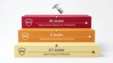
IK Rating Examples:
| IK Rating | Impact Energy | Description |
|---|---|---|
| IK05 | 0.7 Joules | Light impact protection |
| IK08 | 5 Joules | Moderate industrial protection |
| IK10 | 20 Joules | Heavy-duty impact resistance |
Switchgear in industrial environments is exposed to accidental impacts from equipment, tools, or materials. Enclosures that fail this test may crack in ways that create safety hazards or void IP protection. IEC 61439-1 requires verification by testing only — no assessment or comparison is permitted.
9. Rust Resistance
This test exposes metallic enclosure components to controlled corrosion conditions (typically salt spray or humidity chambers) to verify that surface treatments provide adequate protection against rust.
Corrosion degrades the structural integrity and conductivity of enclosures and internal metalwork over time — particularly in outdoor, coastal, or high-humidity installations. Under IEC 61439-1 clause 10.2.2, verification by testing only is required; no assessment or comparison is allowed.
10. Resistance to Damp
This test verifies that the assembly's insulating materials and components maintain their electrical and mechanical properties when exposed to high humidity conditions, typically in a controlled humidity chamber.
Moisture absorption in insulating materials reduces dielectric strength and can cause tracking, leakage currents, or insulation failure. IEEE research confirms that pre-immersing XLPE insulation in water reduces breakdown voltage by more than 50% — a stark illustration of why this test matters for any installation in a humid environment.
11. Resistance of Insulating Materials to Heat
This test verifies that insulating materials used in the assembly do not deform, soften, or lose their insulating properties when exposed to elevated operating temperatures.
Temperature Thresholds:
- Insulating materials on current-carrying parts must withstand 125°C
- All other parts must withstand 70°C
Insulating components that cannot withstand heat degrade prematurely, eroding safety margins and shortening service life. This test must be verified by testing only under clause 10.2.3.
12. Fire Resistance
This test verifies that non-metallic materials used in the enclosure and internal components do not spread flame, containing any localized ignition source within the assembly. Testing follows the glow-wire test per IEC 60695-2-11.
Glow-Wire Temperature Requirements:
- 960°C for live, current-carrying parts
- 650°C for all other parts
Pass Criteria:
- No ignition occurs, OR
- Flame/glow extinguishes within 30 seconds of glow-wire removal
- Tissue paper underneath does not ignite
In a fault scenario involving arcing or overheating, materials that fail this test can accelerate a fire rather than confine it — significantly increasing damage and safety risk. IEC 61439-1 permits verification by either testing or assessment for this test.
13. Mechanical Performance of Assemblies and Fixings
This test verifies the structural integrity of fixing points, mounting hardware, enclosure joints, and assembly connections under mechanical stress to ensure they remain secure during installation, transport, and operation.
Loose or failing fixings can cause busbar misalignment, loss of contact integrity, or enclosure panel failure — a particular concern in vibration-prone environments like industrial plants or transportation infrastructure. Verification must be by testing only.
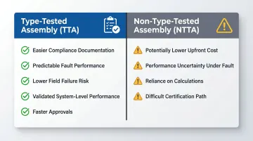
Type-Tested vs. Non-Type-Tested Assemblies: What's the Difference?
A type-tested assembly (TTA) is one where the design has been verified through all applicable IEC 61439-1 tests on a representative prototype, confirming that all components — busbars, protection devices, enclosures, and interconnections — perform together as a validated system.
A non-type-tested assembly (NTTA or partially type-tested assembly) has not undergone the full test suite and instead relies on calculations or individual component ratings as verification.
The practical differences matter most when a project faces fault conditions, inspection scrutiny, or tight approval timelines.
Type-Tested Assemblies:
- Easier compliance documentation
- More predictable performance under fault conditions
- Lower risk of field failures or rework
- Validated system-level performance
- Faster approval processes
Non-Type-Tested Assemblies:
- May be lower in upfront cost
- Greater uncertainty in performance under short-circuit or thermal stress
- Reliance on calculations that may not reflect real-world integration issues
- More difficult certification path for end-users
Understanding which type you're dealing with upfront prevents costly surprises at the inspection stage. When sourcing, confirm the following:
What to Confirm When Sourcing Switchgear:
- Ask the manufacturer for type test certificates
- Confirm which standard governs the design (IEC 61439 for international projects, UL 891 for US installations)
- Verify that the assembly configuration being delivered matches the tested design
- Any deviation from the tested configuration may invalidate type test coverage
DEI Power's UL 891-certified switchboards use standardized, type-tested designs built with Siemens components. All assemblies from 400A to 4000A match the tested configuration referenced in the UL 891 certificate, with detailed submittal documentation included to support procurement and approval.
Conclusion
IEC 61439-1 defines 13 type tests for LV switchgear in two groups — 7 core electrical and mechanical performance tests and 6 additional construction quality tests. Together these tests confirm an assembly is safe, reliable, and fit for purpose before it reaches the field.
Understanding these tests helps contractors, engineers, and facility teams evaluate switchgear quality, ask better questions of manufacturers, and reduce the risk of compliance failures or unplanned downtime on critical power distribution projects.
For US-based projects, specifying UL 891-certified switchboards ensures the assembly has been built to a verified domestic standard. DEI Power manufactures UL 891-certified switchboards at its Ontario, California facility, with in-house engineering support and delivery in 3-5 business days — helping project teams meet schedules without sacrificing code compliance.
Frequently Asked Questions
What is a type tested switchgear?
Type-tested switchgear is an assembly whose design has been verified by the manufacturer through a standardized series of tests (per IEC 61439-1 or equivalent) performed on a representative prototype, confirming the design meets defined safety, performance, and compliance requirements.
What is the difference between type tested panel and non type tested panel?
A type-tested panel has been fully verified through the IEC 61439-1 test suite on a representative design, while a non-type-tested (or partially type-tested) panel relies on calculations or component-level data instead — meaning the complete system performance under fault conditions has not been independently verified.
What is the IEC 60439 type test?
IEC 60439 was the predecessor standard to IEC 61439 for LV switchgear assemblies. IEC 61439 replaced it in 2014 with more rigorous verification requirements, and the same general test categories apply under the updated standard.
What are the 7 electrical tests in order?
The 7 core type tests as defined by IEC 61439-1 are: (1) temperature rise limits, (2) dielectric properties, (3) short-circuit resistance, (4) effectiveness of the protective circuit, (5) clearances and creepage distances, (6) mechanical operation, and (7) degree of protection (IP rating).
How many types of panel testing are there?
IEC 61439-1 defines 13 type tests in two groups: 7 core type tests covering electrical and mechanical performance, and 6 additional tests covering construction quality and material resilience. These are separate from routine tests performed on individual units at the factory.